Check patentability & draft patents in minutes with Patsnap Eureka AI!

Method for controlling display device, display device, method for controlling display system, and display system

a display device and display device technology, applied in the field of display devices, can solve problems such as complicated configuration of display devices

Active Publication Date: 2021-08-24
SEIKO EPSON CORP
View PDF7 Cites 0 Cited by
  • Summary
  • Abstract
  • Description
  • Claims
  • Application Information

AI Technical Summary

Benefits of technology

The present patent text describes a method and system for controlling a display device. The method and system include receiving history information about an operation to a first operation image for a setting of the display device, generating display information used to display a second operation image for a setting of the display device, and transmitting the display information to the terminal device. This allows the display device to display the second operation image based on the history information, without needing to receive a separate instruction from the terminal device. The technical effects include improved efficiency and convenience for users and simplification of the display device's settings process.

Problems solved by technology

However, the system described in JP-A-2012-84045 has a problem in that its configuration is complicated since the information management server is needed as well as the printer and the personal computer.

Method used


Image

  • Method for controlling display device, display device, method for controlling display system, and display system
  • Method for controlling display device, display device, method for controlling display system, and display system
  • Method for controlling display device, display device, method for controlling display system, and display system

Examples


first embodiment

1. First Embodiment

1-1. Outline of Display System

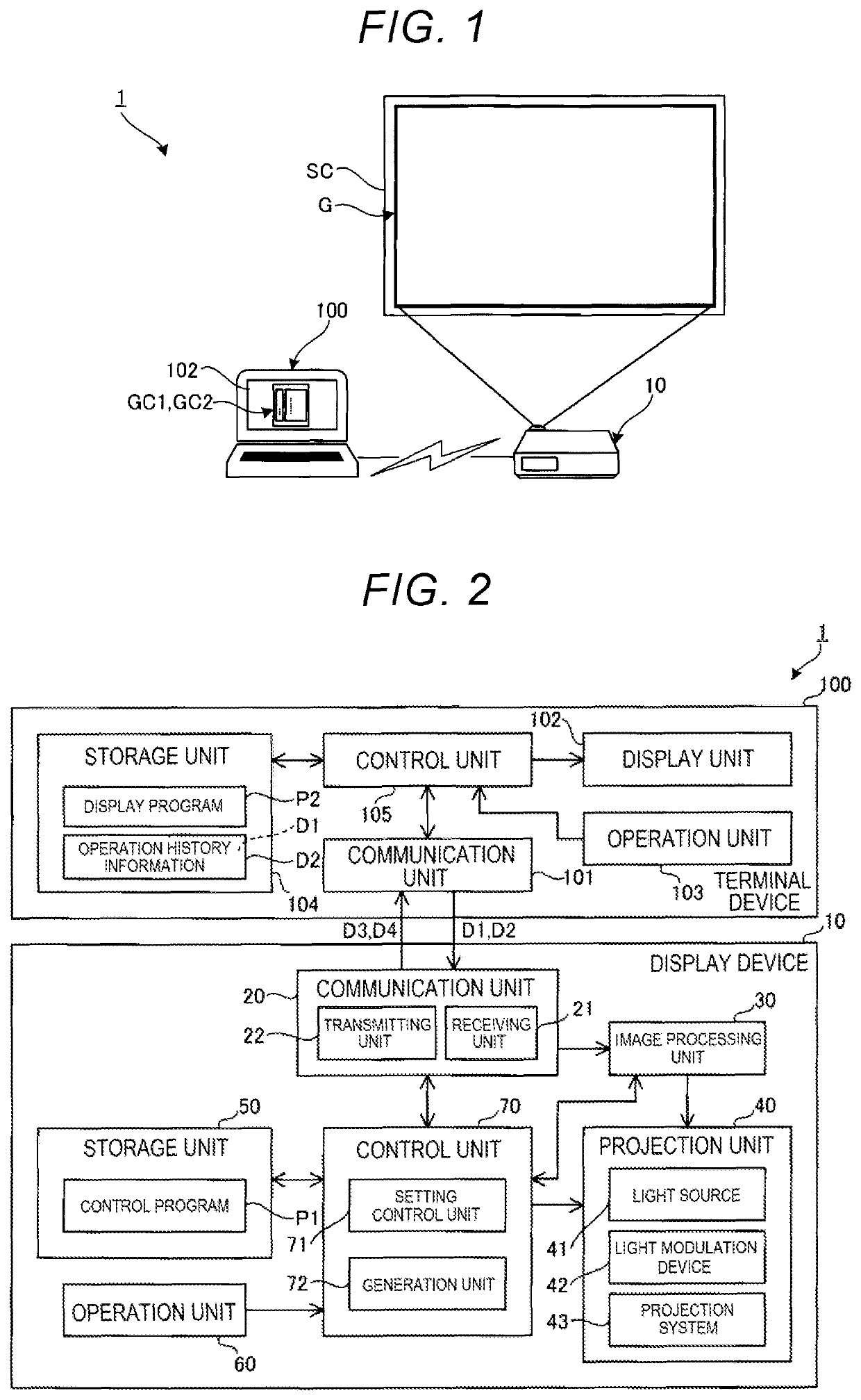
[0019]FIG. 1 schematically shows the external appearance of a display system 1 according to a first embodiment. The display system 1 is a projection system. As shown in FIG. 1, the display system 1 includes a display device 10 and a terminal device 100.

[0020]The display device 10 is communicably coupled to the terminal device 100. This coupling may be wireless or wired. The display device 10 is a projector that can display an image G based on image information from the terminal device 100 or the like, onto a screen SC. The installation site of the screen SC may be, for example, a wall, floor, or table or the like. The installation site of the display device 10 may be, for example, a ceiling, wall, floor, table, or dedicated installation stand or the like.

[0021]The display device 10 can change a setting by an operation at the terminal device 100. The setting is not particularly limited but may be, for example, an image quality setting ...

second embodiment

2. Second Embodiment

[0060]A second embodiment will now be described. This embodiment is similar to the first embodiment except that the content of the display information D4 varies depending on whether the multi-projection function is used or not. In the description below, the second embodiment is described mainly in terms of the difference from the first embodiment, and similar matters are not described. In each drawing used for the description of the second embodiment, configurations similar to those in the first embodiment are denoted by the same reference signs.

[0061]FIG. 7 schematically shows the external appearance of a display system 1A according to the second embodiment. The display system 1A is a system having the multi-projection function. As shown in FIG. 7, the display system 1A has display devices 10a and 10b, and the terminal device 100. The display device 10a displays an image Ga on the screen SC. The display device 10b is communicably coupled to the display device 10...

modification examples

3. Modification Examples

[0068]The method for controlling the display device, the display device, the method for controlling the display system, and the display system according to the present disclosure have been described above, based on the illustrated embodiments. However, the present disclosure is not limited to these embodiments. The configuration of each part according to the present disclosure can be replaced by an arbitrary configuration that achieves a function similar to that in the embodiments, and an arbitrary configuration can be added thereto. Also, arbitrary configurations in the embodiments may be combined together.

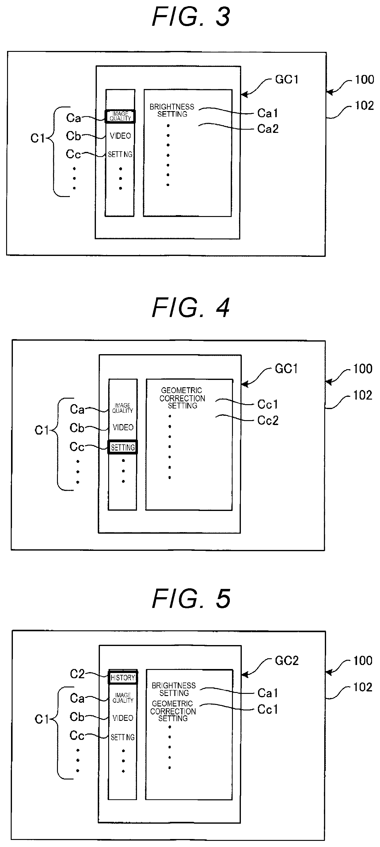
[0069]In the embodiments, the case where the second operation image GC2 includes the entire content of the first operation image GC1 is described. However, the second operation image GC2 may not include a setting item of the first operation image GC1. In this case, the second operation image GC2 may be provided with a separate menu for displaying the setti...


PUM


Abstract

A method for controlling a display device includes: receiving history information about an operation to a first operation image for a setting of the display device, from a terminal device displaying the first operation image; generating display information used to display a second operation image for a setting of the display device, using the history information; and transmitting the display information to the terminal device.

Description

[0001]The present application is based on, and claims priority from JP Application Serial Number 2018-227898, filed Dec. 5, 2018, the disclosure of which is hereby incorporated by reference herein in its entirety.BACKGROUND1. Technical Field[0002]The present disclosure relates to a method for controlling a display device, a display device, a method for controlling a display system, and a display system.2. Related Art[0003]A system that can make various settings of an apparatus such as a projector, using a terminal device communicably coupled to the apparatus, is known. For example, in a system described in JP-A-2012-84045, a setting item of print processing by a printer is displayed on a display of a personal computer. In this system, an information management server is communicably coupled to each of the personal computer and the printer. The information management server manages the frequency of use of a setting item of the print processing by the printer. The personal computer ac...

Claims


Application Information

Patent Timeline
Patent Type & Authority Patents(United States)
IPC IPC(8): G06F3/14G06F3/0481
CPCG06F3/1423G06F3/0481G06F3/1431G06F3/1446H04N9/3147H04N9/3179H04N21/4122H04N21/43615H04N21/4854
Inventor ITO, SHIGEHITO
Owner SEIKO EPSON CORP
Features
  • R&D
  • Intellectual Property
  • Life Sciences
  • Materials
  • Tech Scout
  • Unparalleled Data Quality
  • Higher Quality Content
  • 60% Fewer Hallucinations
Learn More