Core wire for multi-core cables and multi-core cable
- Summary
- Abstract
- Description
- Claims
- Application Information
AI Technical Summary
Benefits of technology
Problems solved by technology
Method used
Image

Examples
first embodiment
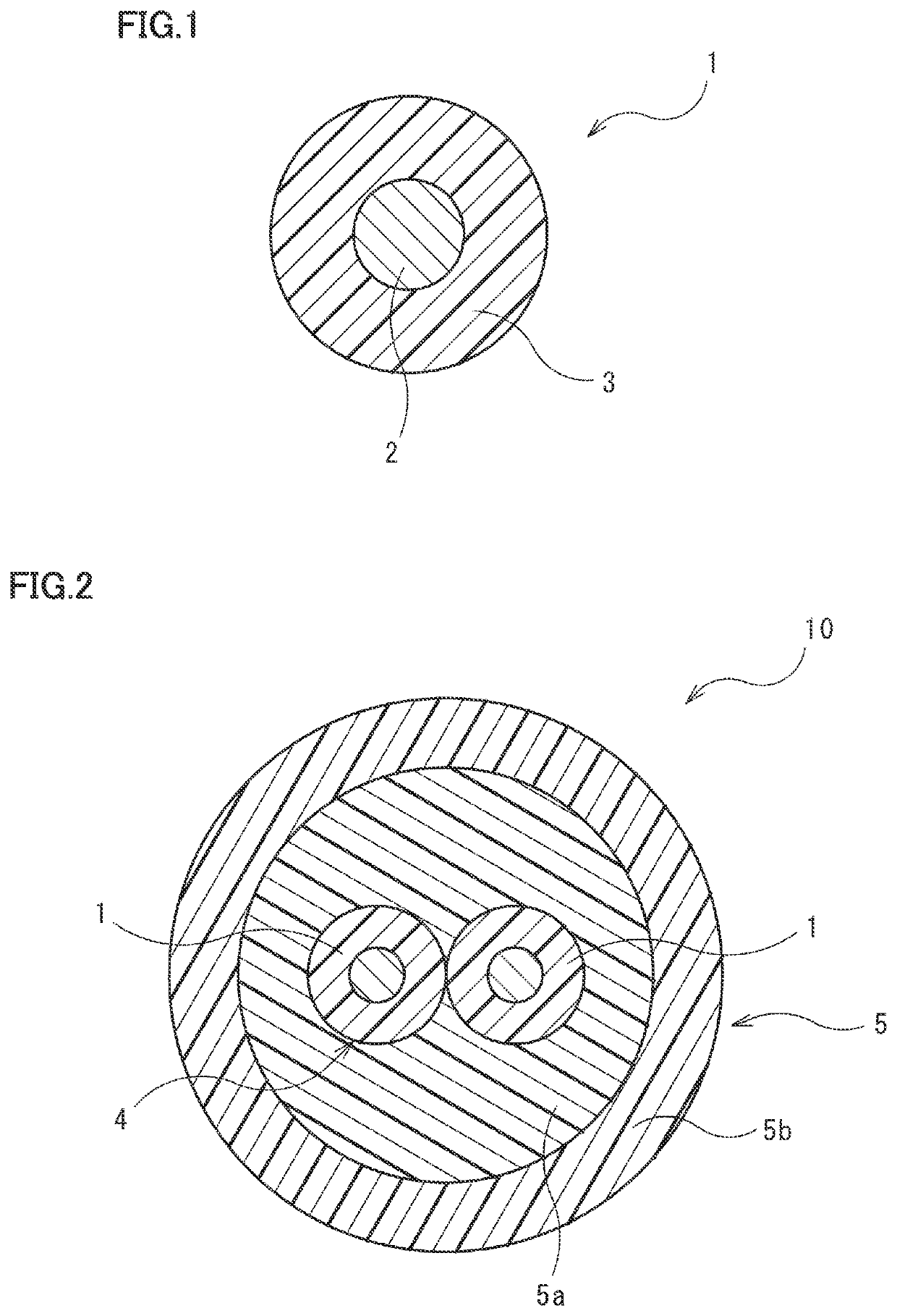
[0026]A core wire 1 illustrated in FIG. 1 is an insulated wire to be used for preparing a multi-core cable that includes a cable core and a sheath layer provided around the cable core. The cable core is obtained by twisting the core wires 1. The core wire 1 includes a conductor 2 in the form of a wire and an insulating layer 3 which is a protective layer coated on the outer peripheral surface of the conductor 2.
[0027]The cross-sectional shape of the core wire 1 is not particularly limited, it may be circular, for example. When the cross-sectional shape of the core wire 1 is circular, the average outer diameter may be, for example, 1 mm or more and 10 mm or less according to different applications. The method for measuring the average outer diameter of the cross section of the core wire is not particularly limited. For example, a caliper is used to measure the outer diameter of the core wire at any 3 positions, and the average value of the outer diameters measured at 3 positions may ...
second embodiment
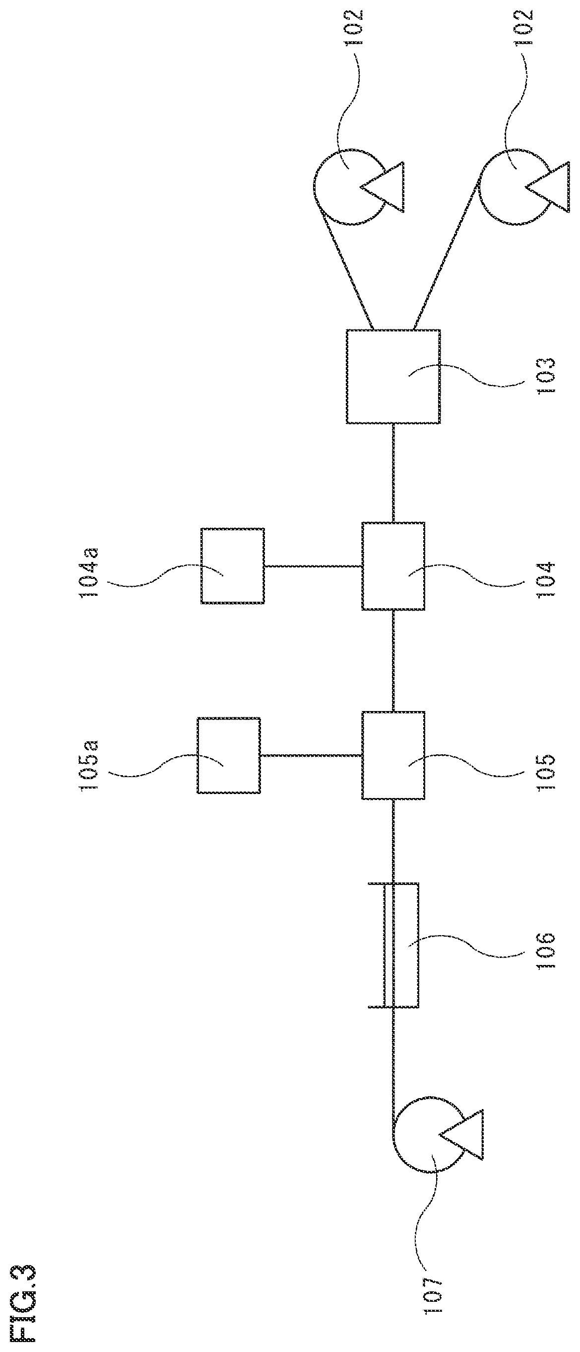
[0057]A multi-core cable 10 illustrated in FIG. 2 includes a cable core 4 which is obtained by twisting a plurality of the core wires 1 illustrated in FIG. 1, and a sheath layer 5 which is provided around the cable core 4. The sheath layer 5 has an inner sheath layer (intervening layer) 5a and an outer sheath layer (outer coating) 5b. The multi-core cable 10 may be suitably used as a cable for transmitting an electrical signal to a motor that drives a brake caliper of an electric parking brake.
[0058]The outer diameter of the multi-core cable 10 may be appropriately adjusted according to various applications. The lower limit of the outer diameter is preferably 6 mm, and more preferably 8 mm. On the other hand, the upper limit of the outer diameter of the multi-core cable 10 is preferably 16 mm, more preferably 14 mm, further preferably 12 mm, and particularly preferably 10 mm.
[0059]
[0060]The cable core 4 is obtained by twisting two of the core wires 1 having the same diameter in pair...
third embodiment
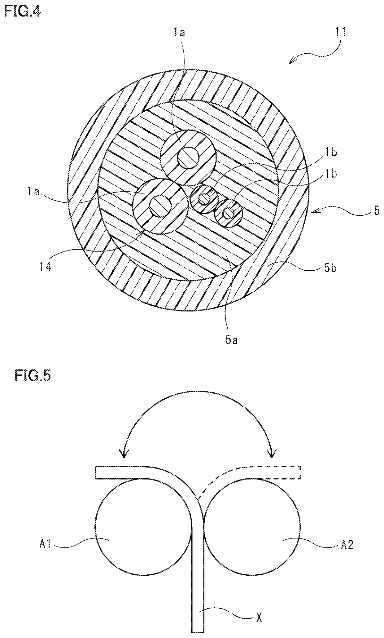
[0083]A multi-core cable 11 illustrated in FIG. 4 includes a cable core 14 which is obtained by twisting a plurality of the core wires illustrated in FIG. 1, and a sheath layer 5 which is provided around the cable core 14. The multi-core cable 11 is different from the multi-core cable 10 illustrated in FIG. 2 in that the cable core 14 is obtained by twisting a plurality of core wires having different diameters. The multi-core cable 11 may be suitably used not only as a signal cable for an electric parking brake but also as a signal cable for transmitting electrical signals so as to control the operation of an anti-lock brake system (ABS). Since the sheath layer 5 is the same as the sheath layer 5 of the multi-core cable 10 illustrated in FIG. 2, it is assigned with the same reference numeral, and the description thereof will not be repeated.
[0084]
[0085]The cable core 14 is obtained by twisting two of the first core wires 1a having the same diameter and two of the second core wires 1...
PUM
| Property | Measurement | Unit |
|---|---|---|
| Temperature | aaaaa | aaaaa |
| Temperature | aaaaa | aaaaa |
| Temperature | aaaaa | aaaaa |
Abstract
Description
Claims
Application Information
 - R&D Engineer
- R&D Manager
- IP Professional
- Industry Leading Data Capabilities
- Powerful AI technology
- Patent DNA Extraction
Browse by: Latest US Patents, China's latest patents, Technical Efficacy Thesaurus, Application Domain, Technology Topic.
© 2024 PatSnap. All rights reserved.Legal|Privacy policy|Modern Slavery Act Transparency Statement|Sitemap