Illumination system for an endoscope

an endoscope and endoscope technology, applied in the field of endoscope illumination system, can solve the problems of difficult to provide the desired light distribution in front of the tip part, strict light restriction, etc., and achieve the effect of reducing the amount of electronics in the waste to be handled and more waste hea

Active Publication Date: 2021-09-07
AMBU AS
View PDF29 Cites 0 Cited by
  • Summary
  • Abstract
  • Description
  • Claims
  • Application Information

AI Technical Summary

Benefits of technology

[0009]By the use of such an elongated single-piece light guide in the illumination arrangement in the tip part, it becomes possible to provide a desired light distribution in front of the tip part, while at the same time overcoming one or more of the other prior art drawbacks mentioned above. Furthermore, the use of a light fiber to conduct the light to the light guide reduces the number of electrical wires to be drawn from the handle to the tip part. Also, using a single-piece light guide allows manufacture of the single-piece from a rigid material, as compared to the non-rigid light fiber, in turn making the handling in manufacture and assembly easier.
[0020]According to a specifically preferred embodiment, the endoscope comprises a light source connected to the handle. Having the light source outside the handle, rather than inside, allows the light source to be placed at a location where excess heat from the light source may efficiently be dissipated. Accordingly, as compared to a location within the handle or even in the tip of the endoscope a more powerful light source producing more waste heat may be utilized without any discomfort to the operator or the patient. Furthermore, more space will be available allowing for other types of light sources as compared to the prior art in which LED's are currently used in the tip part. Furthermore, having the light source in a non-disposable part, allows the light source and at least some of the associated electronics to be reused, reduces the amount of electronics in the waste to be handled.

Problems solved by technology

Though providing LEDs in the tip of the endoscope is in many ways efficient and has largely proved itself a success, there are however some minor drawbacks that speak against this approach to illumination.
One is that the LEDs themselves take up space in the tip part, where space is sparse.
Furthermore, the LEDs and any associated electronics dissipate heat, which puts strict restrictions on the amount of light which can be produced by LEDs in the tip part itself, when the endoscope is inserted into a patient.
Since LEDs are more or less point light sources, providing a desired light distribution in front of the tip part is therefore difficult, and may need a number of LEDs.

Method used


Image

  • Illumination system for an endoscope
  • Illumination system for an endoscope
  • Illumination system for an endoscope

Examples


first embodiment

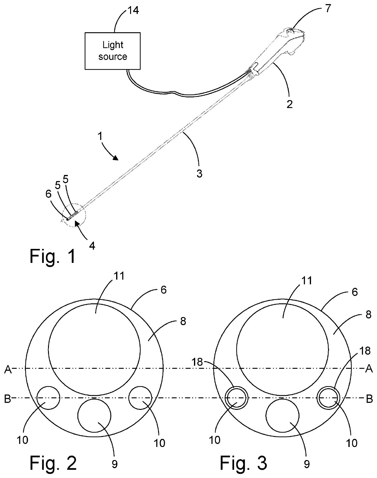
[0023]FIG. 2 shows an end view of the distal tip of the endoscope according to the invention,

second embodiment

[0024]FIG. 3 shows an end view of the distal tip of the endoscope according to the invention,

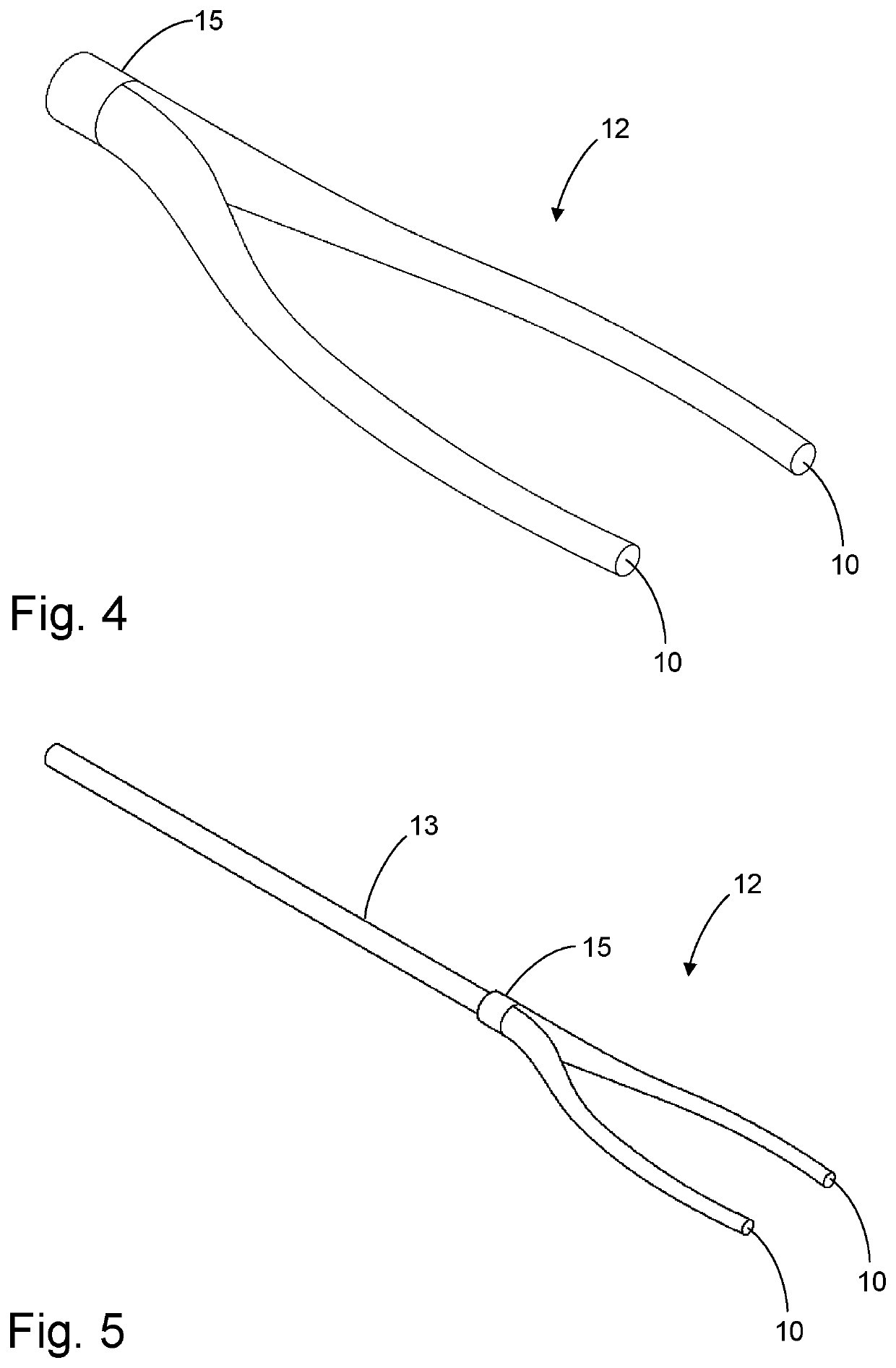
[0025]FIG. 4 shows a light guide according to the invention,

[0026]FIG. 5 shows the light guide of FIG. 4 connected to a light fiber,

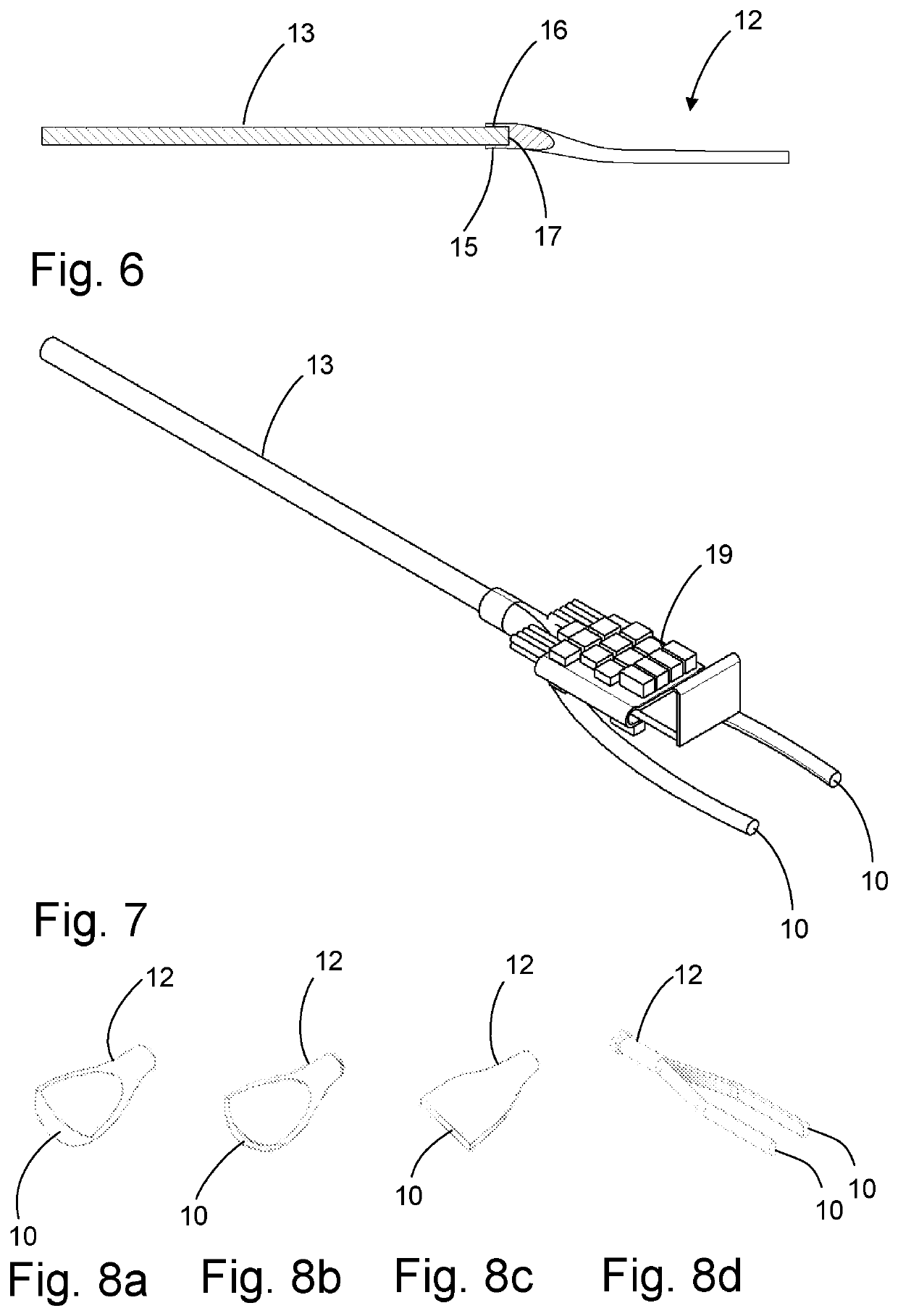
[0027]FIG. 6 shows a cross-section of the light guide and light fiber of FIG. 5,

[0028]FIG. 7 shows the light guide and light fiber of FIG. 5 in conjunction with an electronics module

[0029]FIGS. 8a-8d show alternative embodiment of the light guide according to the invention,

[0030]FIG. 9 shows a further embodiment of the invention with a tapering conical part, and

[0031]FIG. 10 shows a further embodiment of the invention with an expanding conical part.


PUM


Abstract

An endoscope includes a hollow handle housing and an insertion tube including a tip part at the distal end of the endoscope. The tip part includes an illumination arrangement with an elongated single-piece light guide having a proximal light guide end and at least one distal light guide end, wherein the proximal light guide end is adapted for receiving at least one light fiber. The at least one distal light guide end has an end surface adapted for emitting the light from a light source. The cross-section of the proximal light guide end differs from the cross-section of the at least another part of the light guide.

Description

CROSS-REFERENCE TO RELATED APPLICATIONS[0001]This application claims priority under 35 U.S.C. § 119(b) from European Application No. 17206235, filed on Dec. 8, 2017, which is expressly incorporated herein by reference in its entirety.TECHNICAL FIELD[0002]The present invention relates to an illumination system for an endoscope, more specifically to an endoscope comprising an insertion tube with a tip part comprising an illumination arrangement adapted for emitting light emanating from a light source.BACKGROUND OF THE DISCLOSURE[0003]As the name indicates, endoscopes, are used for seeing inside things, such as lungs or other human body cavities of a patient. Modern endoscopes are therefore typically equipped with a least one camera or similar image capturing device at the distal tip of the endoscope. Provided that sufficient light is present, this allows the operator to see where the endoscope is steered and to set the target of interest once the tip has been advanced thereto. This th...

Claims


Application Information

Patent Timeline
Patent Type & Authority Patents(United States)
IPC IPC(8): A61B1/00A61B1/07G02B23/24A61B1/05A61B1/06F21V8/00
CPCA61B1/07A61B1/0011A61B1/00096A61B1/00117A61B1/00126A61B1/05A61B1/0669G02B23/2461A61B1/0017A61B1/00167G02B6/0006A61B1/06A61B1/0684G02B23/2469
Inventor SØRENSEN, MORTENJENSEN, THOMAS BACHGAARD
Owner AMBU AS
Why Eureka
Try Eureka