
Structure for preventing formation of dead point for cam wheel and strapping device using the same

a technology of dead points and strapping devices, which is applied in the directions of packaging, bundling machine details, and application of binding materials, etc., can solve the problems of lowering work efficiency, no implementable solutions have been proposed, and failing to provide actual real-time dealing measures, so as to prevent the generation of unexpected dead points from interrupting the work flow. , the effect of improving work efficiency

Active Publication Date: 2021-09-07
PANTECH INT
View PDF5 Cites 2 Cited by
  • Summary
  • Abstract
  • Description
  • Claims
  • Application Information

AI Technical Summary

Benefits of technology

The invention aims to improve work efficiency by preventing unexpected dead points that can interrupt work flow. This is achieved by designing a structure that prevents the formation of a dead point for a cam wheel and a strapping device using the same.

Problems solved by technology

However, US Patent Publication No. 2011 / 0056389 A1 fails to provide actual implementable measures for dealing with the problem.
Indeed, in practice, no implementable solutions have yet been proposed.
But during the operations, the occurrences of these dead points would interrupt the rhythm and work flow of the engineers, lowering work efficiency.

Method used


Image

  • Structure for preventing formation of dead point for cam wheel and strapping device using the same
  • Structure for preventing formation of dead point for cam wheel and strapping device using the same
  • Structure for preventing formation of dead point for cam wheel and strapping device using the same

Examples


Embodiment Construction

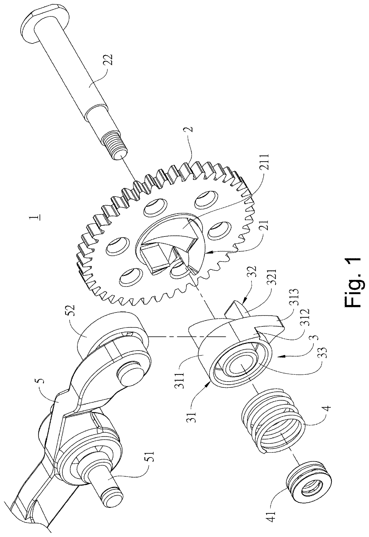
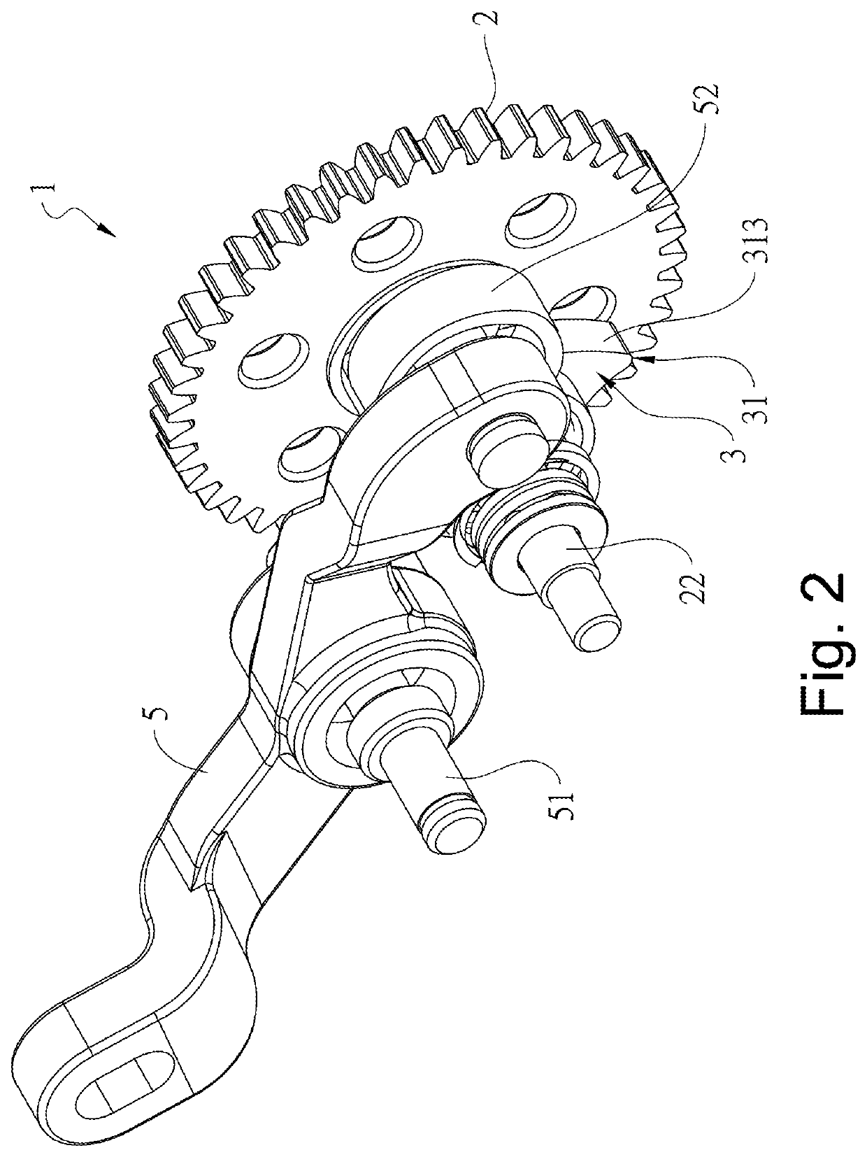
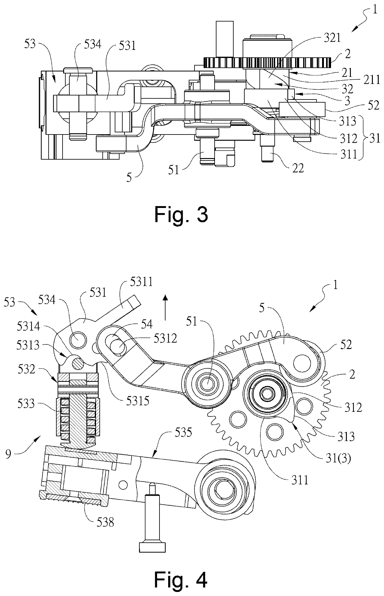
[0022]Referring to FIGS. 1 to 4, a structure for preventing the formation of a dead point for a cam wheel 1 in accordance with a first embodiment of the present invention is illustrated. The structure 1 includes a driving wheel 2, a pressing portion 21, a cam wheel 3, a restoring piece 4, a stopping piece 41 and a swinging piece 5. The driving wheel 2 is a spur gear with a pressing portion 21 provided co-axially at one side of the driving wheel. The pressing portion 21 consists of a plurality of thorn teeth 211 arranged on one side of the driving wheel 2 in a form of circular array. The teeth surfaces of the thorn teeth 211 are all facing a side of the cam wheel 3. The cam wheel 3 is pivoted on the same pivot shaft 22 as the driving wheel 2 in a way of being axially movable with respect to the driving wheel 2.

[0023]The cam wheel 3 includes a cam portion 31, a pushed portion 32 and a positioning portion 33 on the same axis. The cam portion 31 includes a circumferential surface 311, a...


PUM


Abstract

A structure for preventing the formation of a dead point for a cam wheel includes a driving wheel with a pressing portion provided at one side thereof for pushing a pushed portion of the cam wheel. When the cam wheel is moved over a distance while rotating simultaneously, a cam portion of the cam wheel pushes one end of the swinging piece. When the one end of the swinging piece is pushed to be apart from the outer periphery of the cam wheel, a restoring piece axially pushes the cam wheel back to its original position. A strapping device includes the above structure, a housing, a first transmission assembly, a second transmission assembly and a third transmission assembly. Tensioning of a circular strap, rapid friction bonding and cutting are sequentially performed by the transmissions of the first to third assemblies, respectively.

Description

FIELD OF THE INVENTION[0001]The present invention relates to a structure for preventing the formation of a dead point for a cam wheel and a strapping device using the same and, more specifically, a structure and a strapping device that improve work efficiency by preventing unexpected dead points from forming during the strapping operation.BACKGROUND OF THE INVENTION[0002]A common handheld strapping device essentially involves tensioning of a plastic strap with a feeder wheel and subsequent sealing and cutting of an overlapped area of the two ends of the plastic strap for quick and effective wrapping of packaged goods. More specifically, after placing the overlapped strap in a tensioning zone, the feeder wheel is rotated upon the actuation of a start-up button to allow the tensioning of the relaxed strap. Once the strap is tensioned, the sealing of the overlapped layers of the strap can take place by ways of lateral reciprocating movements of a sealing head, which is activated by pre...

Claims


Application Information

Patent Timeline
Patent Type & Authority Patents(United States)
IPC IPC(8): B65B13/22B65B13/02B65B13/18
CPCB65B13/22B65B13/025B65B13/185
Inventor YANG, MING SHIH
Owner PANTECH INT
Learn More