Resonance tube of horn

a technology of resonance tube and horn, which is applied in the direction of electrical transducers, instruments, transportation and packaging, etc., can solve the problems of inability to remove foreign matter such as water, insufficient sound pressure required as horn sound cannot be obtained,

Active Publication Date: 2021-09-07
MAZDA MOTOR CORP
View PDF12 Cites 0 Cited by
  • Summary
  • Abstract
  • Description
  • Claims
  • Application Information

AI Technical Summary

Benefits of technology

[0023]The present invention can provide the resonance tube of the horn, the resonance tube being capable of outputting the chord having the adequate sound pressure.

Problems solved by technology

The reason why the resonance tube is provided is because if the sound generated by the diaphragm is directly output, adequate sound pressure required as horn sound cannot be obtained.
Since the resonance tube has a spiral shape, there is a problem that foreign matter such as water cannot be removed if the foreign matter enters and accumulates in the resonance tube.

Method used


Image

  • Resonance tube of horn
  • Resonance tube of horn
  • Resonance tube of horn

Examples


modified examples

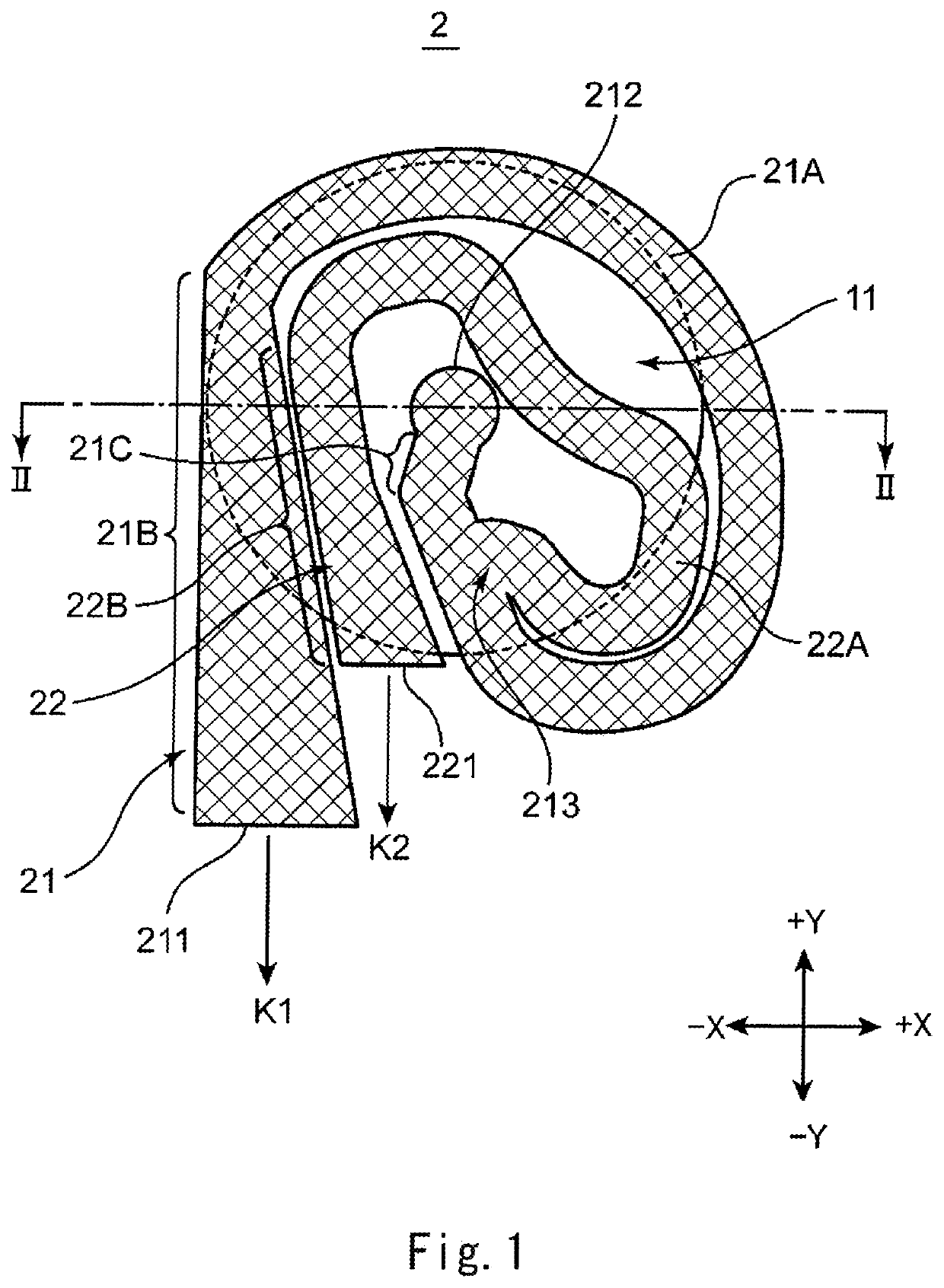
[0091](1) The foregoing has explained that as shown in FIG. 1, the second resonance tube 22 branches from the first resonance tube 21. However, the first resonance tube 21 may branch from the second resonance tube 22. In this case, the entire length of the branched first resonance tube 21 is only required to be made longer than the entire length of the second resonance tube 22 such that the branched first resonance tube 21 resonates with the first sound having the lower fundamental frequency than the second sound.

[0092](2) In FIG. 1, the second opening surface 221 is displaced from the first opening surface 211 in the +Y direction along the normal direction K1 but may be displaced in the −Y direction. To be specific, the first and second opening surfaces 211 and 221 are only required to be displaced from each other in the Y direction, and there is no relationship in which a predetermined one of the first and second opening surfaces 211 and 221 must be displaced from the other of the...


PUM


Abstract

A resonance tube of a horn according to one aspect of the present invention includes a first resonance tube and a second resonance tube branching from the first resonance tube at a branching portion. The first resonance tube is a resonance tube that resonates with a first sound contained in a chord generated by a diaphragm. The first resonance tube includes: an input opening surface to which the chord is input; and a first opening surface from which the first sound is output. The second resonance tube is a resonance tube that resonates with a second sound contained in the chord. The second resonance tube includes a second opening surface from which the second sound is output. The second opening surface is displaced from the first opening surface in a normal direction K1.

Description

TECHNICAL FIELD[0001]The present invention relates to a resonance tube of a horn mounted on a vehicle.BACKGROUND ART[0002]A horn, which vibrates a diaphragm with a movable core and outputs the sound generated by the diaphragm to the outside through a resonance tube, is mounted on a vehicle. The reason why the resonance tube is provided is because if the sound generated by the diaphragm is directly output, adequate sound pressure required as horn sound cannot be obtained. Since the resonance tube has a spiral shape, there is a problem that foreign matter such as water cannot be removed if the foreign matter enters and accumulates in the resonance tube. Thus, PTL 1 discloses an electric horn for a vehicle, in which a foreign matter entry prevention member is affixed to a sound wave outlet opening portion of a resonance tube to prevent foreign matter flying from the front side of the vehicle from entering the resonance tube.CITATION LISTPatent Literature[0003]PTL 1: Japanese Laid-Open ...

Claims


Application Information

Patent Timeline
Patent Type & Authority Patents(United States)
IPC IPC(8): G10K11/22B60Q5/00G10K9/13G10K9/22G10K13/00H04R1/28
CPCG10K11/22B60Q5/00G10K9/13G10K9/22G10K13/00H04R1/2865H04R2499/13
Inventor INO, HISANOBUOHSUGI, IKUYOSAKIYAMA, MASAAKI
Owner MAZDA MOTOR CORP
Why Eureka
Try Eureka