Connector

a technology of connecting rods and connecting rods, applied in the direction of wound springs, mechanical equipment, machines/engines, etc., can solve the problems of shielding body damage or unusual sound generation

Active Publication Date: 2021-09-14
NICHIAS CORP
View PDF16 Cites 0 Cited by
  • Summary
  • Abstract
  • Description
  • Claims
  • Application Information

AI Technical Summary

Benefits of technology

[0022]According to the present invention, it is possible to provide a connector in which a buffer member including a spiral-shaped wire deforms less in the course of use, in which no middle portion protrudes to the outside, and in which a coupling member is less likely to collide with a vibrating body even if a shielding body is vibrated.

Problems solved by technology

When the shielding body is vibrated by the vibrating body, either directly or indirectly, the shielding body may be damaged or generate unusual sound.

Method used


Image

  • Connector
  • Connector
  • Connector

Examples


first embodiment

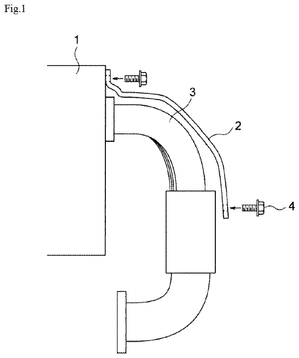
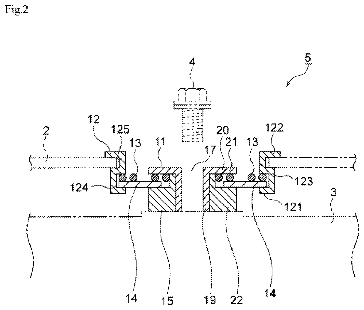
[0055]A connector according to the present invention is a connector that is provided to a connection between a vibrating body that is a vibration source and a plate-like shielding body that is attached to the vibrating body, the connector including:

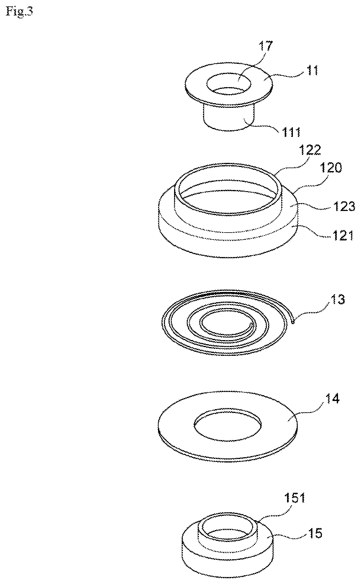
[0056]a first buffer member that includes a spiral-shaped wire in a plan view:

[0057]a second buffer member that has a substantially annular and flat plate-like shape, that is capable of warping in a thickness direction, and that is stacked with the first buffer member;

[0058]a collar member that includes a cylindrical portion having an insertion hole for a fixing member for attaching the connector to the vibrating body, the cylindrical portion being surrounded by the first buffer member and the second buffer member, a first flange facing a radially inner side of the first buffer member, and a second flange facing a radially inner side of the second buffer member, the first and the second flanges both protruding from the cylindrical portion...

second embodiment

[0087]A connector according to the present invention is a connector that is provided to a connection between a vibrating body that is a vibration source and a plate-like shielding body that is attached to the vibrating body, the connector including:

[0088]a first buffer member that includes a spiral-shaped wire in a plan view;

[0089]a second buffer member that has a substantially annular and flat plate-like shape, that is capable of warping in a thickness direction, and that is stacked with the first buffer member;

[0090]a third buffer member that includes a spiral-shaped wire in a plan view, and that is stacked with the second buffer member on a side opposite to the first buffer member;

[0091]a collar member that includes a cylindrical portion having an insertion hole for a fixing member for attaching the connector to the vibrating body, the cylindrical portion being surrounded by the first buffer member, the second buffer member, and the third buffer member, a first flange facing a ra...


PUM


Abstract

A connector includes a first buffer member that includes a spiral-shaped wire, a second buffer member that has a substantially annular and flat plate-like shape capable of warping in a thickness direction, a collar member that includes a first flange facing a radially inner side of the first buffer member, and a second flange facing a radially inner side of the second buffer member, and a coupling member. A gap for allowing the second buffer member to move in a radial direction is formed between the second buffer member and a cylindrical portion. A distance between a position of a surface of the second flange and a position of a lowest end of the collar member is greater than a distance between a position of a surface of the first flange and the position of the surface of the second flange in a view in an axial direction.

Description

TECHNICAL FIELD[0001]The present invention relates to a connector that is provided to a connection between a vibrating body and a plate-like shielding body attached to the vibrating body.BACKGROUND ART[0002]Engines, transmissions, exhaust manifolds attached to engines, turbochargers, heat-exchanging components, and electrical rotating machines are vibrating bodies that themselves vibrate, or that are vibrated by being affected by engines. Various components are attached to such a vibrating body. One example of such attached components is a shielding body such as an exhaust manifold cover or a heat insulator.[0003]Such a shielding body generally includes two metal sheets facing each other, and is configured to prevent physical energies such as heat and sound emitted from the vibrating body from being transmitted to other components near the engine or the outside of the vehicle. When the shielding body is vibrated by the vibrating body, either directly or indirectly, the shielding bod...

Claims


Application Information

Patent Timeline
Patent Type & Authority Patents(United States)
IPC IPC(8): F16F3/04F16F15/06F01N13/10F01N13/18F02B77/13F16F1/10F16F1/12
CPCF16F15/06F01N13/102F01N13/1811F02B77/13F16F1/10F16F1/12F01N2260/20F02B77/11F16F15/067F16F2230/0005F16F3/04F16F1/32F16F3/02
Inventor KATO, TADAKATSUMISHINA, SAKAEYOSHINO, KEIICHIENAMI, KOKI
Owner NICHIAS CORP
Why Eureka
Try Eureka