Eureka AIR delivers breakthrough ideas for toughest innovation challenges, trusted by R&D personnel around the world.

Liquid separator

Active Publication Date: 2021-09-28
ATLAS COPCO AIRPOWER NV
View PDF61 Cites 0 Cited by
  • Summary
  • Abstract
  • Description
  • Claims
  • Application Information

AI Technical Summary

Benefits of technology

The present invention aims to provide a cheap and light liquid separator that can be used in water-injected compressors to generate oil-free compressed air with a cheaper machine. The technical effect is the improved efficiency and cost-effectiveness of the compressor system.

Problems solved by technology

An advantage is that by providing the inlet in the lid, it is no longer necessary to provide the inlet in the housing wall, which is detrimental to the strength of this wall.

Method used


Image

  • Liquid separator
  • Liquid separator
  • Liquid separator

Examples


Embodiment Construction

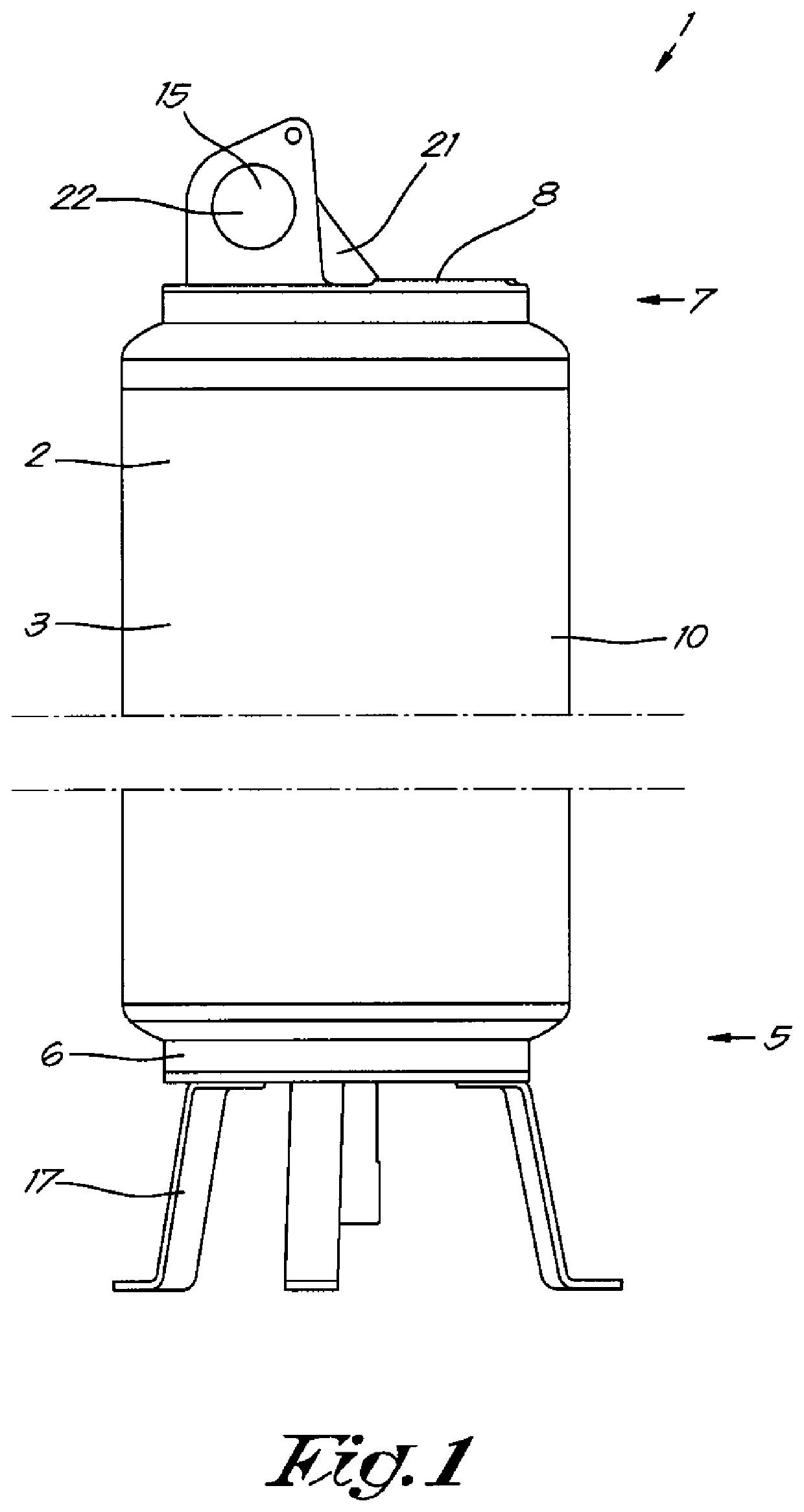
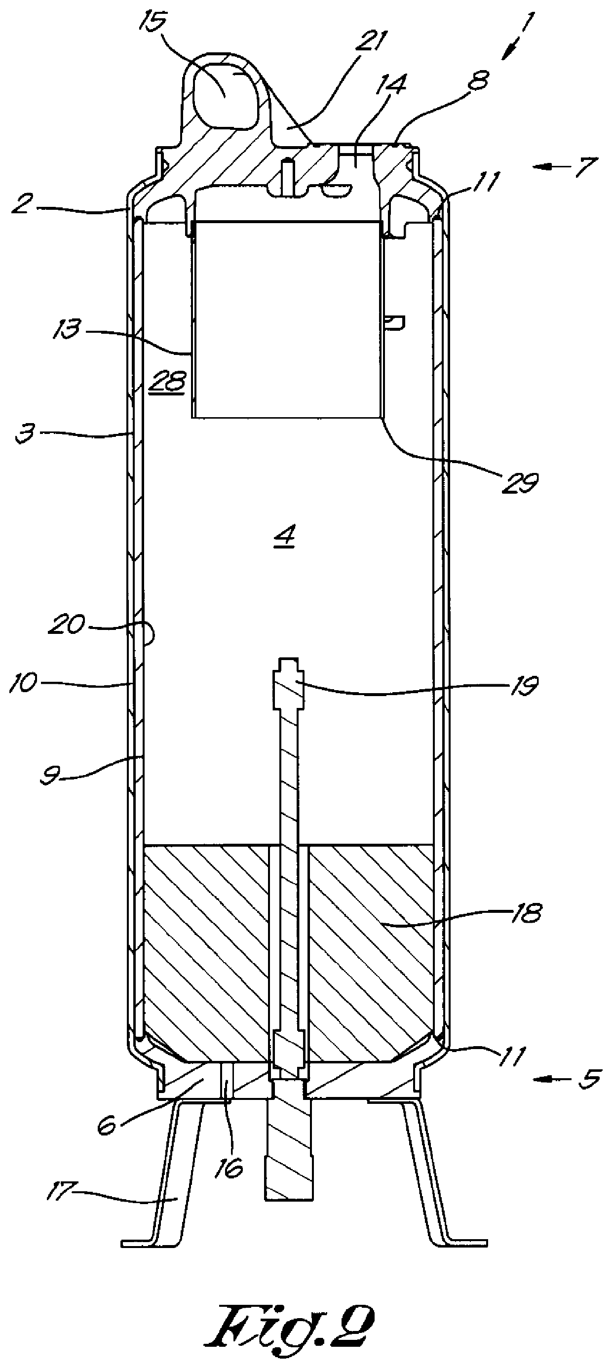
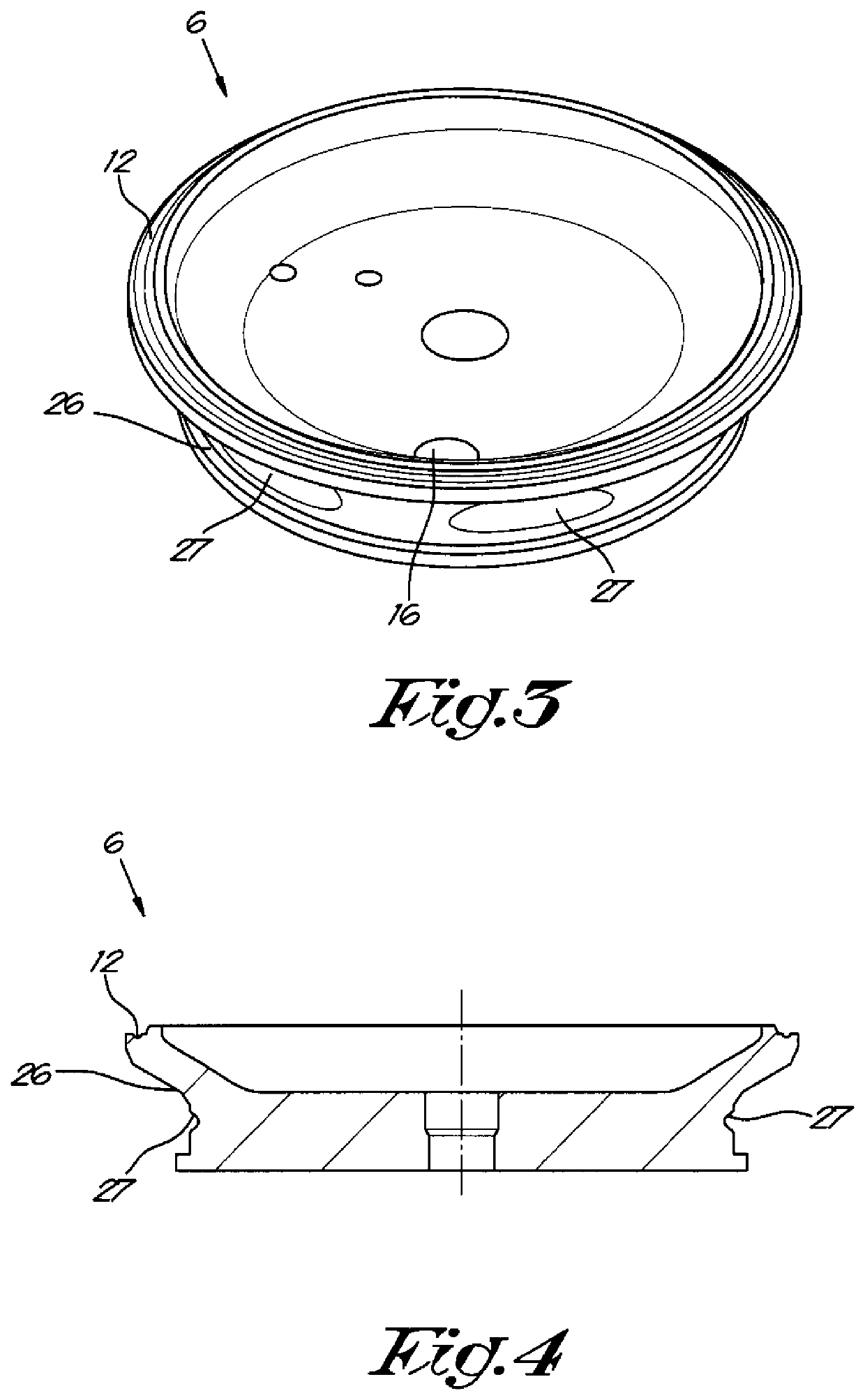
[0059]The liquid separator 1 according to the invention as schematically represented in FIGS. 1 and 2 primarily comprises a housing 2 which consists of an at least partially cylindrical wall 3 defining a separation chamber 4 which is closed at one end, the bottom side 5, by means of a base 6 and at the other end, the top side 7, by means of a lid 8.

[0060]As shown in the example shown in FIG. 2, the wall 3 of the housing 2 is made up of a sleeve 9, around which a composite 10 is fitted or wrapped.

[0061]The sleeve 9 is made up of a plastic or polymer such as, for example, HDPE, yet it is not excluded that another material is used.

[0062]The composite 10 is made up of glass fiber, aramid or carbon fiber in an epoxy resin matrix or the like.

[0063]In this case, both the base 6 and the lid 8 are made of anodized aluminum. That material is cheaper and lighter than, for example, stainless steel.

[0064]To ensure a good sealing, seals 11 are provided between the base 6 and the lid 8 on the one ...


PUM

PropertyMeasurementUnit
Angleaaaaaaaaaa
Pressureaaaaaaaaaa
Flow rateaaaaaaaaaa

Abstract

Liquid separator provided with a housing which includes an at least partially cylindrical wall defining a separation chamber, closed at one end by a base and at the other end by a lid in which there is a gas outlet for the discharge of the treated gas. A shield is provided in the separation chamber surrounding the gas outlet in the separation chamber from the aforementioned lid. The liquid separator has an inlet for a liquid-gas mixture to be treated. The inlet is located in the lid so that the liquid-gas mixture tangentially enters the separation chamber in the space between the wall and the shield.

Description

[0001]More specifically, the invention is intended for separating liquid, such as for example water, from compressed gas from a compressor.BACKGROUND OF THE INVENTION[0002]Oil-injected compressors are already known, with oil being injected into the rotor chamber for lubrication, sealing and cooling. As a consequence, the compressed air will contain oil.[0003]However, for the pharmaceutical industry, the paint industry and in food related and electronics applications it is necessary to provide oil-free compressed air.[0004]Therefore, filters are provided after the compressor element to filter the oil out of the air.[0005]However, these filters will never remove all of the oil out of the air, so that this air cannot be used in critical or highly demanding applications in the aforesaid sectors, as even the smallest amount of oil in pharmaceutical, paint, electronics or food applications makes the products unusable and everything must be destroyed.[0006]In addition, there is a risk of f...

Claims


Application Information

Patent Timeline
IPC IPC(8): B01D50/00B01D45/16B04C3/04B04C3/06B01D45/12B01D45/08B04C3/00B04C5/13
CPCB01D45/16B01D45/08B01D45/12B04C3/04B04C3/06B01D50/002B01D2313/20B01D2313/21B04C5/13B04C2003/006B01D50/20B01D2313/201
Inventor FRAGUELA YANEZ, PABLO MANUELRABAEY, ELISABETH ANIKA SIMONPOTTERS, TOM ANDRE JENNYVRIENS, VIKTOR MAURITS INGRIDMARIEN, KAREN ANNA LEON
Owner ATLAS COPCO AIRPOWER NV
Why Eureka
Eureka Blog
Learn More