Highly secure optical key access control system

Active Publication Date: 2021-09-28
KHLOPKOV KONSTANTIN
View PDF9 Cites 4 Cited by
  • Summary
  • Abstract
  • Description
  • Claims
  • Application Information

AI Technical Summary

Benefits of technology

The present invention is a highly secure optical key access control system that uses a light source and an optical element to verify the identity of a user. The light beam is directed through the optical element from several different directions, making it difficult for potential forgeries to mimic the refraction images. The location and direction of the light beam relative to the optical key are unique, making it difficult for forgeries to calculate the desired sets of pre-authmed refraction images. The system is designed to prevent unauthorized access, ensuring secure and efficient control over optical keys.

Problems solved by technology

Existing access control systems based on traditional hardware based keys all have certain properties that make it possible one way or another to copy or mimic the key and therefore permit unauthorized access to controlled premises or computer databases.
Existing access control systems based on computer software are vulnerable to hackers with sufficient knowledge of computer systems and social engineering.
While being functional for its intended purpose, this system appears vulnerable to mimicking the key in terms of the key-lock system.
In spite of the extreme difficulties of copying optical properties of a prism, a potential forger having a particular optical key at hand and sufficient knowledge can one way or another mimic or copy not the prism but the authorized scatter pattern to deceive scatter pattern detecting module of the lock and so to get unauthorized access to protected premises.

Method used


Image

  • Highly secure optical key access control system
  • Highly secure optical key access control system
  • Highly secure optical key access control system

Examples


Embodiment Construction

[0017]The inventor provides a highly secure access control system, and more particularly, methods and apparatus utilizing unique optical properties of non-duplicatable transparent objects to secure premises and computer databases. An Optical key and an access module as the terms used in this specification refer to the apparatus by which user can get access to secure premises or computer databases using the optical key as a key and the access module as a lock.

[0018]The present invention is described in enabled detail in the following examples, which may represent more than one embodiment of the present invention.

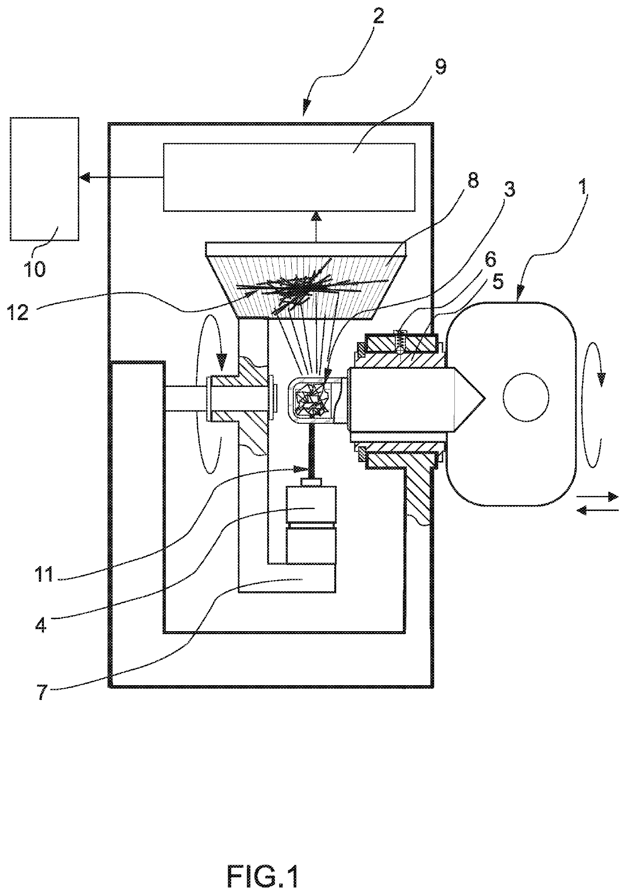
[0019]FIG. 1 is a schematic diagram illustrating the method of the highly secure optical key access control system according to an embodiment of the present invention.

[0020]In this example an access control system comprises:

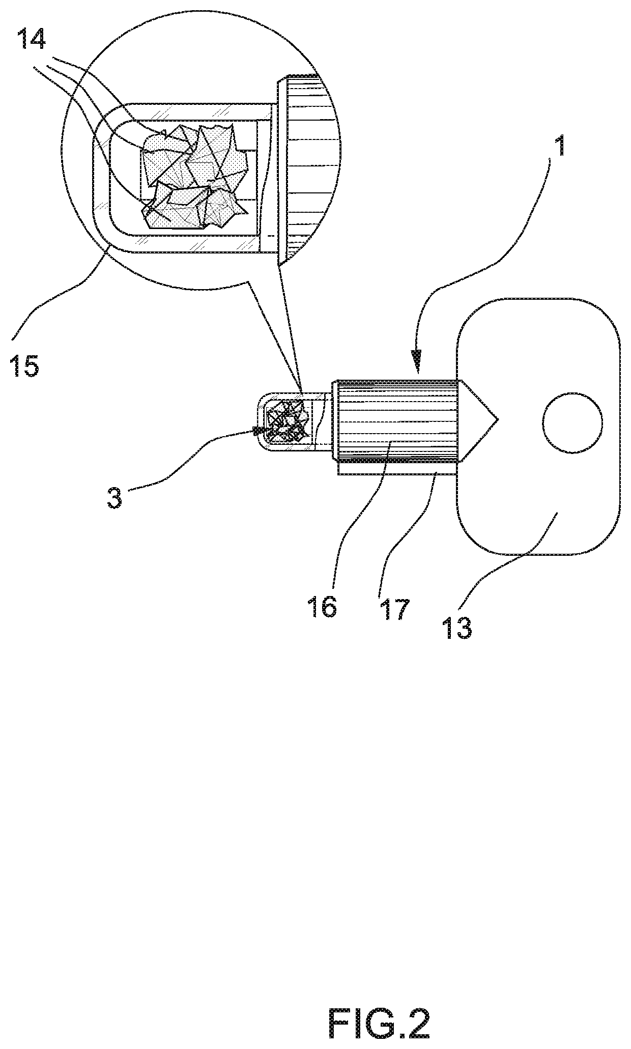
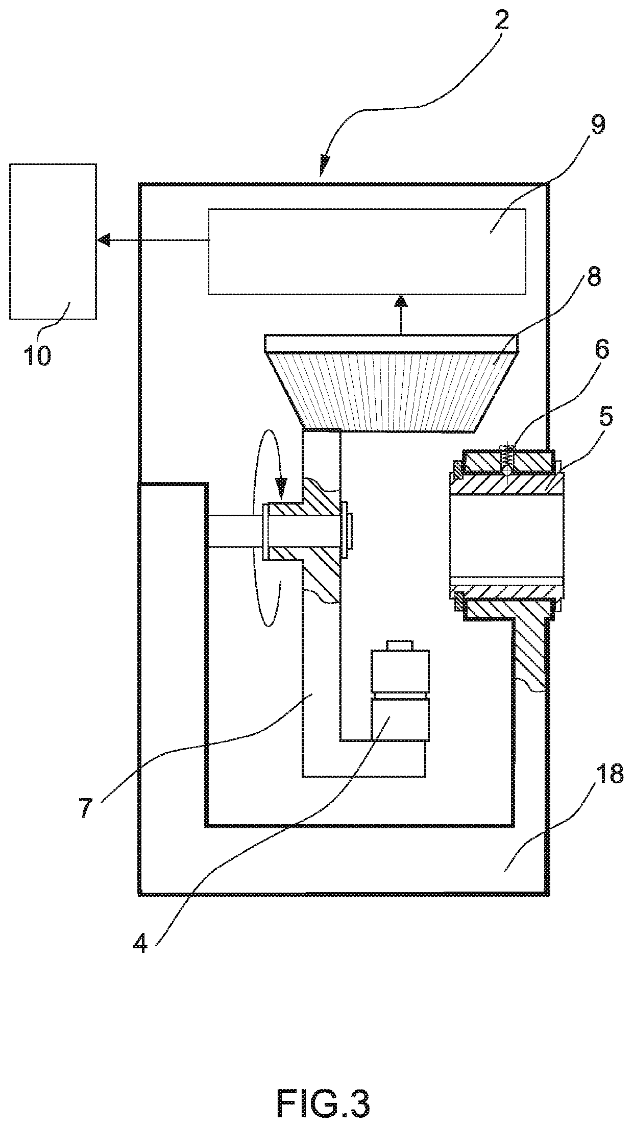
[0021]an optical key 1 with an optical element 3 and an access module 2 comprising a light source 4, means 5 and 6 of positioning the optical key inside t...


PUM


Abstract

A highly secure optical key access control system utilizing unique optical refraction properties of non-duplicatable transparent objects to secure premises or computer databases is disclosed. The said access control system includes an optical key containing an optical element with unique refraction properties and an access module comprising a light source, an image catching array and an electronic processor. The optical element of the optical key is inserted into the access module between the light source and the image catching array at the initial and then several following prearranged positions and a resulting set of unique refraction images appearing on the surface of the image catching array is processed with the electronic processor for comparison against preauthorized sets of refraction images to grant or deny access to the protected premises or protected computer databases.

Description

BACKGROUND OF THE INVENTION1. Field of the Invention[0001]The present invention relates to the field of highly secure access control systems, and more particularly, methods and apparatus utilizing unique optical refraction properties of non-duplicatable transparent objects to secure premises and computer databases.2. Discussion of the State of the Art[0002]Existing access control systems based on traditional hardware based keys all have certain properties that make it possible one way or another to copy or mimic the key and therefore permit unauthorized access to controlled premises or computer databases.[0003]Existing access control systems based on computer software are vulnerable to hackers with sufficient knowledge of computer systems and social engineering.[0004]Existing electro-optical and magnetic card access control systems are easy to operate and cost effective. They possess a certain level of security but have the same shortcomings: if a person with sufficient knowledge ge...

Claims


Application Information

Patent Timeline
IPC IPC(8): E05B49/00G06F21/62E05B19/24E05B17/10G06F16/583G05B1/00G07C9/00G06K7/10G06K19/06
CPCE05B49/006E05B17/10E05B19/24G05B1/00G06F16/583G06F21/62G06K7/10G07C9/00182G06K2019/0629G07C2009/00785G06F21/35G06F21/6218
Inventor KHLOPKOV, KONSTANTIN
Owner KHLOPKOV KONSTANTIN
Why Eureka
Try Eureka