
Fixing apparatus with pressing member having connected pores in elastic layer

a technology of elastic layer and fixing apparatus, which is applied in the direction of electrographic process, instruments, other domestic objects, etc., can solve the problems of large impact, deviation of degree of parallel, and difficult elimination, so as to reduce the biasing force of film and improve the durability

Active Publication Date: 2021-10-05
CANON KK
View PDF27 Cites 2 Cited by
  • Summary
  • Abstract
  • Description
  • Claims
  • Application Information

AI Technical Summary

Benefits of technology

The present invention is a fixing apparatus that is designed to be stronger and more durable. The apparatus achieves this by reducing the force that a film applies when it is bent or stretched.

Problems solved by technology

Examples of causes of the biasing force include eccentricity of the outer diameter of the film and the pressing roller that rotationally drives the film and eccentricity of a pressing force that presses the film against the pressing roller.
However, the factor having the greatest impact is deviation of degree of parallel, that is, deviation of alignment between the film and the pressing roller.
This deviation of degree of parallel derives from the degree of parallel and warpage of the frame that is caused when assembling constituent parts of the fixing apparatus, and it is difficult to eliminate this.
When the biasing force of the film become large, an edge portion of the film abuts a flange, and due to the load on the edge portion, the edge portion might wear, break, tear, or bend to be damaged.
That is, in some cases, even in a state in which adjustment was made such that the degree of parallel between the film and the pressing roller was not deviated, the film rotated in accordance with the pressing roller was biased to abut a flange and was thus damaged.

Method used


Image

  • Fixing apparatus with pressing member having connected pores in elastic layer
  • Fixing apparatus with pressing member having connected pores in elastic layer
  • Fixing apparatus with pressing member having connected pores in elastic layer

Examples


Embodiment Construction

Exemplary Embodiment

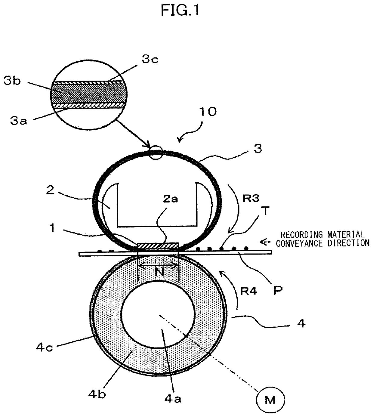
[0039]An exemplary embodiment of the present invention will be described in detail below with reference to drawings.

Image Forming Apparatus

[0040]FIG. 12 is a diagram schematically illustrating a configuration of an example of an image forming apparatus, which is an image forming apparatus of an electrophotographic system. This image forming apparatus includes an electrophotographic photosensitive member 101 that rotates, a charging unit 102 and an image exposing unit 103 serving as electrostatic latent image forming portions for the photosensitive member 101, and a developing unit 104 that develops the electrostatic latent image on the photosensitive member 101 as a toner image serving as a developer image. In addition, this image forming apparatus includes a transfer portion 105 that transfers the toner image on the photosensitive member 101 onto a sheet-shaped recording material P, and a cleaning portion 106 that cleans the surface of the photosensitive member ...


PUM

PropertyMeasurementUnit
temperaturesaaaaaaaaaa
temperatureaaaaaaaaaa

Abstract

A fixing apparatus includes an endless belt, and a pressing member including a base body and an elastic layer formed on the base body. A plurality of pore portions connected to each other are provided in the elastic layer. In a case where a binary image is generated from a three-dimensional image of the elastic layer, a threshold value X μm corresponding to opening processing with which a number of pores derived from the pore portions takes a maximum value is obtained, and then pores derived from the pore portions in the elastic layer are extracted by performing opening processing with a threshold value of 2X μm, an average value of angles θ is 120° or larger and smaller than 150°.

Description

BACKGROUND OF THE INVENTIONField of the Invention[0001]The present invention relates to a fixing apparatus incorporated in an image forming apparatus such as a copier, a printer, or a facsimile machine, and a manufacturing method for a pressing member.Description of the Related Art[0002]An image forming apparatus of an electrophotographic system includes a fixing apparatus that fixes a toner image to a recording material by heating and pressurizing the toner image formed on the recording material. The recording material will be hereinafter referred to as a sheet. This fixing apparatus includes fixing members such as a heating roller / belt and a pressing roller / belt, and performs a fixing process at a fixing nip portion, which is a position at which these are in pressure contact.[0003]Examples of the fixing apparatus include an apparatus of a film heating system or a belt heating system. This apparatus includes a heater as a heating member, or a heat source, that includes a heating re...

Claims


Application Information

Patent Timeline
Patent Type & Authority Patents(United States)
IPC IPC(8): G03G15/20B29C44/12B29C44/42B29L31/00B29C33/56B29K83/00B29K507/04B29C44/34
CPCG03G15/206G03G15/2053G03G15/2064B29C33/56B29C44/12B29C44/3415B29C44/42B29K2083/005B29K2507/04B29L2031/767G03G15/2057G03G2215/2035G03G2215/2051G03G2215/2054
Inventor ASAKA, AKESHIAKIYAMA, NAOKISUGIMOTO, HIROTOMURAMATSU, HIROKIMIYAHARA, YASUHIROKOBAYASHI, NORIAKI
Owner CANON KK
Learn More