
Control device for internal combustion engine

a control device and internal combustion engine technology, applied in the direction of electric control, valve drive, combustion-air/fuel-air treatment, etc., can solve the problems of unburned hc (hydrocarbon) generated due to incomplete combustion, unburned hc is likely to be emitted to the outside, etc., and achieve the effect of reliable introduction into the combustion chamber

Active Publication Date: 2021-10-26
AISIN CORP
View PDF10 Cites 0 Cited by
  • Summary
  • Abstract
  • Description
  • Claims
  • Application Information

AI Technical Summary

Benefits of technology

[0007]However, a conventional control device for an internal combustion engine can reduce the amount of emitted unburned HC only after the first cycle including initial combustion, that is, only in and after the second cycle. That is to say, the emission of unburned HC cannot be reliably suppressed during initial combustion during which a large amount of fuel is injected, and there is room for improvement.
[0010]According to this configuration, in the intake process in which the piston moves from the top dead center position to the bottom dead center position, the timing of opening the exhaust valve is overlapped with the timing of opening the intake valve. As a result, exhaust gas that contains unburned HC in the exhaust passage can be returned to the combustion chamber to reburn the unburned HC, and the amount of emitted unburned HC can be reduced.
[0011]Also, according to this configuration, the bypass passage is provided that connects the exhaust passage of one of the cylinders that is in the exhaust process to an exhaust passage of another one of the cylinders that is in the intake process at the same timing as the aforementioned exhaust passage. Thus, exhaust gas that contains unburned HC in the one of the cylinders is introduced into the combustion chamber in the another one of the cylinders in a state where the exhaust valve is open in the overlap period. As a result, not only is exhaust gas that contains unburned HC in the exhaust passage of the another one of the cylinders returned to the combustion chamber, but also exhaust gas that contains unburned HC in the exhaust passage of the one of the cylinders introduced into the combustion chamber in the another one of the cylinders. Accordingly, for example, during initial combustion during which a large amount of fuel is injected and a large amount of unburned HC is emitted, unburned HC emitted from the one of the cylinders is introduced into the combustion chamber in the another one of the cylinders and is reburned, and thus, the amount of emitted unburned HC can be further reduced.
[0012]Thus, it is possible to provide a control device for an internal combustion engine with which the emission of unburned HC can be further suppressed.
[0018]According to this configuration, since the electromagnetic valve is open before initial combustion chamber is performed in one of the cylinders, exhaust gas with high pressure at an early stage of the exhaust process in the one of the cylinders is introduced into the combustion chamber in another one of the cylinders in a state where the exhaust valve is open in the overlap period. As a result, exhaust gas that contains a large amount of unburned HC generated during initial combustion is reburned, and the amount of emitted unburned HC can be reliably reduced. Also, according to this configuration, since the electromagnetic valve is closed at the timing at which the exhaust valve is closed for the first time after initial combustion is performed in one of the cylinders, exchange of exhaust gas between the cylinders is prohibited after exhaust gas has been introduced from the one of the cylinders in which initial combustion is to occur into another one of the cylinders. As a result, after the electromagnetic valve has been closed, internal EGR is introduced by overlapping, in each of the cylinders, the timing of opening the exhaust valve with the timing of opening the intake valve, and the amount of fresh air to be taken in is increased by canceling the overlapping, and thus, control can be performed while giving consideration to the balance between a reduction in the emission of unburned HC and the combustion stability.
[0020]Since the intake pressure is high in a high-load low-rotation period, it is difficult to introduce internal EGR in the combustion chambers in the cylinders. If the electromagnetic valve is open in the period in the high-load low-rotation state, as in this configuration, exhaust gas with high pressure at the early stage of the exhaust process in the exhaust passage of one of the cylinders is introduced into the exhaust passage of another one of the cylinders in which the exhaust valve is open in the overlap period. As a result, the flow rate of the internal EGR that is returned to the combustion chamber in the another one of the cylinders increases, and thus, the internal EGR can be reliably introduced to the combustion chamber. Accordingly, the emission of unburned HC can be suppressed.

Problems solved by technology

When an engine is started, a large amount of injected fuel is introduced into a combustion chamber in order to reliably perform initial combustion in cylinders, and the amount of unburned HC (hydrocarbon) generated due to incomplete combustion is likely to increase.
Also, since a catalyst for cleaning unburned HC is not yet warm nor activated when the engine is started, unburned HC is likely to be emitted to the outside.

Method used


Image

  • Control device for internal combustion engine
  • Control device for internal combustion engine
  • Control device for internal combustion engine

Examples


Embodiment Construction

[0031]Hereinafter, an embodiment of the present invention will be described based on the drawings. However, the present invention is not limited to the following embodiment, and various modifications may be made without departing from the gist of the invention.

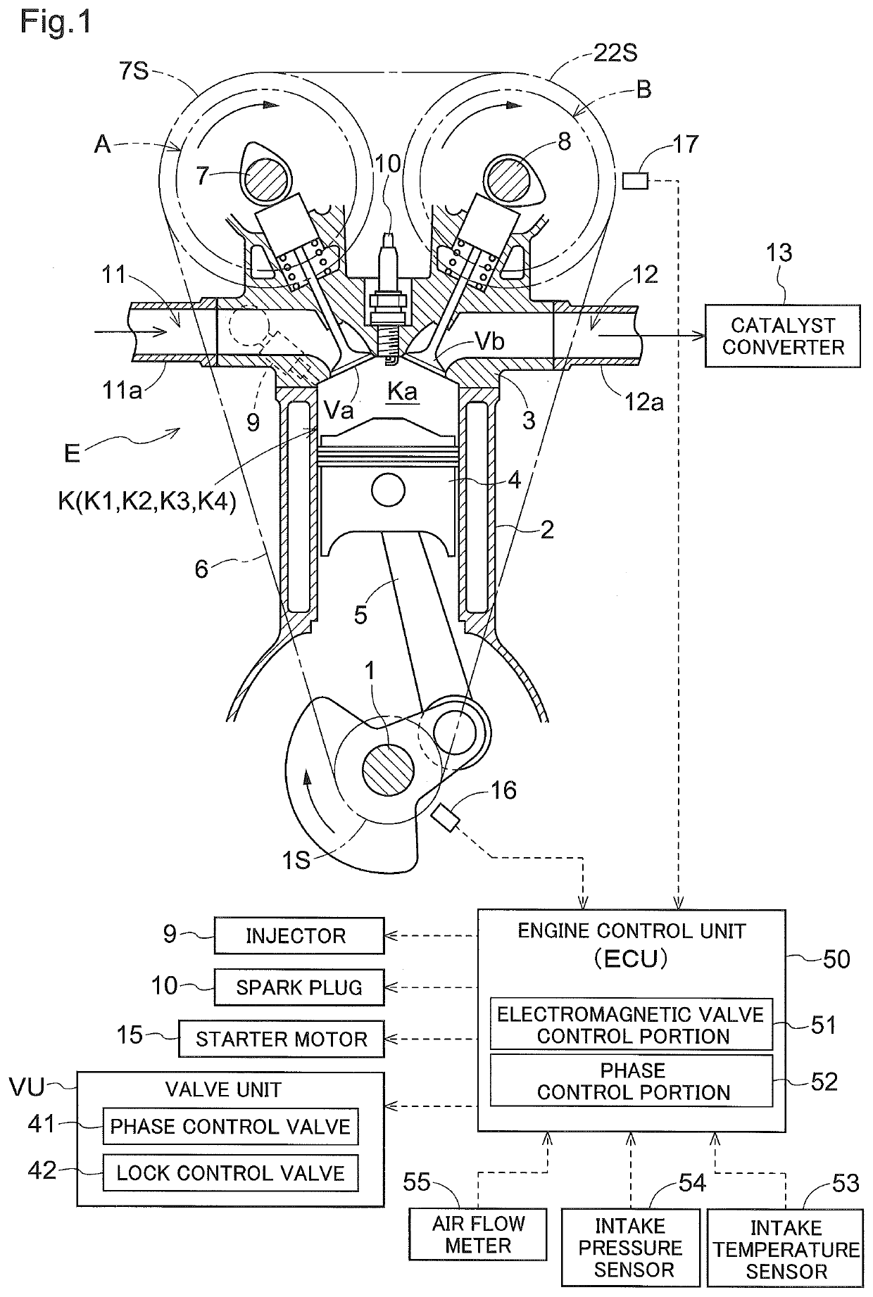
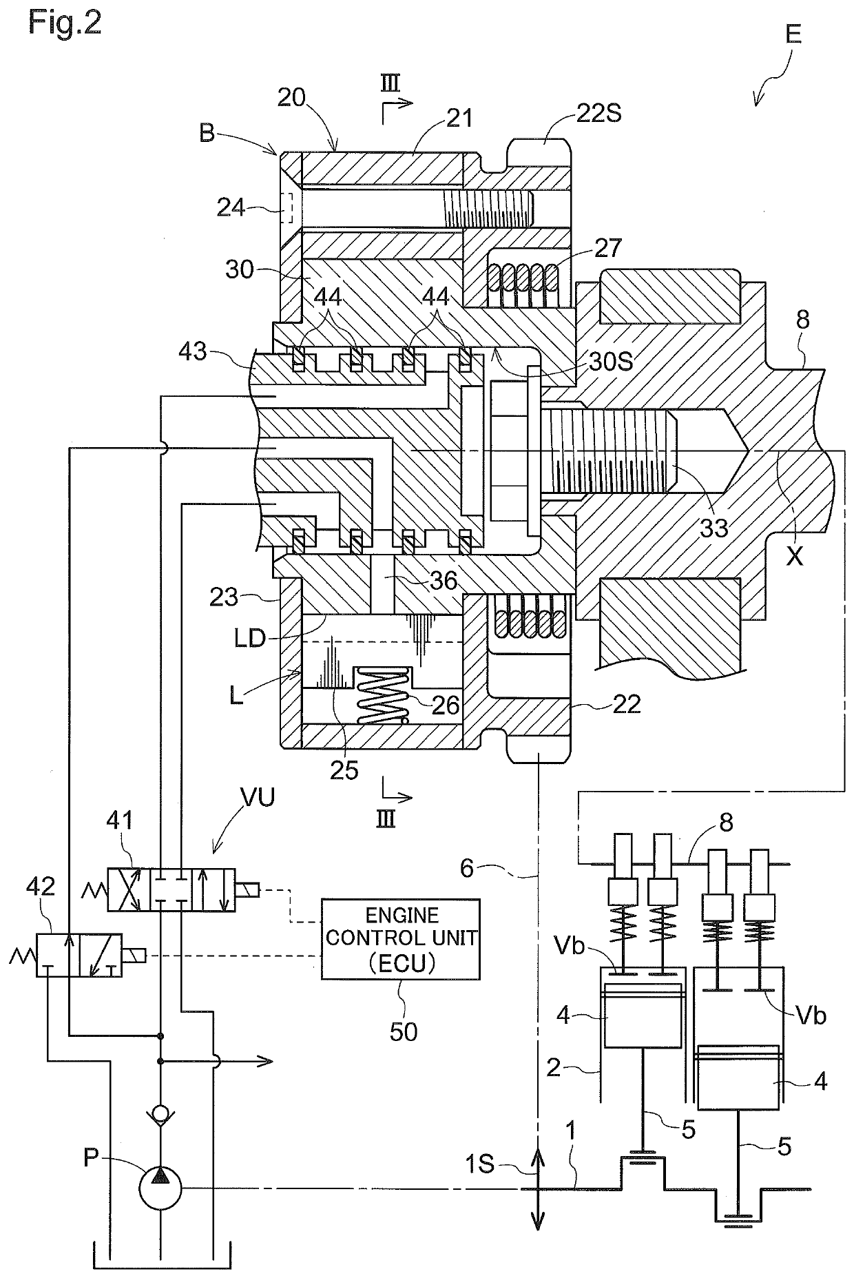
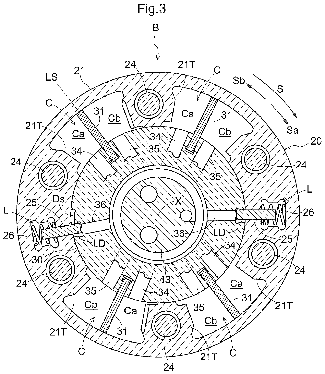
[0032]As shown in FIGS. 1 and 2, a control device for an internal combustion engine includes an engine E (an example of an internal combustion engine), an intake-side valve opening-closing timing control device A for setting timings of opening and closing each intake valve Va in the engine E, an exhaust-side valve opening-closing timing control device B for setting timings of opening and closing each exhaust valve Vb in the engine E, and an engine control unit (ECU) 50 for controlling the engine E.

(Internal Combustion Engine)

[0033]The engine E shown in FIG. 1 is provided in a vehicle, such as a passenger car. The engine E includes four cylinders K, a piston 4, a crankshaft 1, an intake passage 11, an exhaust passage 12, an int...


PUM


Abstract

A control device for an internal combustion engine includes an internal combustion engine and a valve opening-closing timing control device. The valve opening-closing timing control device has a phase adjustment mechanism for setting a relative rotation phase of a driving-side rotator and a driven-side rotator. The phase adjustment mechanism overlaps a timing of opening an intake valve with a timing of opening an exhaust valve, by setting, in a predetermined period, the relative rotation phase such that the exhaust valve closes after a top dead center position has been reached, and a bypass passage is provided that connects an exhaust passage of one cylinder that is in an exhaust process to the exhaust passage of another cylinder that is in an intake process at the same time as the exhaust process.

Description

TECHNICAL FIELD[0001]The present invention relates to a control device for an internal combustion engine and relates specifically to a technology for suppressing emission of unburned HC.BACKGROUND ART[0002]When an engine is started, a large amount of injected fuel is introduced into a combustion chamber in order to reliably perform initial combustion in cylinders, and the amount of unburned HC (hydrocarbon) generated due to incomplete combustion is likely to increase. Also, since a catalyst for cleaning unburned HC is not yet warm nor activated when the engine is started, unburned HC is likely to be emitted to the outside.[0003]Patent Document 1 discloses a technology called internal EGR (Exhaust Gas Recirculation) for overlapping a timing of opening an intake valve with a timing of opening an exhaust valve after initial combustion and before the next combustion in each cylinder, thereby returning exhaust gas that contains unburned HC in an exhaust passage to the combustion chamber ...

Claims


Application Information

Patent Timeline
Patent Type & Authority Patents(United States)
IPC IPC(8): F02D13/02F02M26/14F01L1/04F01N13/10F02M26/53F01L1/047F02M35/10
CPCF02D13/0215F01L1/047F01N13/10F02M26/14F02M26/53F02M35/10222Y02T10/12F01L2001/0537F01L1/3442F01L2001/3443F01L2001/34473F01L2001/34456F01L2001/34483F01L2001/34479F01L2001/34496F01N3/0835F01N3/103F02D13/0219F02D13/0261F02D41/008F02D41/006F02D2200/0414F02D2200/0406F02D41/18F01L2001/34463F01L2001/34466F01L2250/02Y02T10/40
Inventor FUJIMOTO, SEIICHIKANEKO, MASAAKITANAKA, HIROKAZUKAMIYA, SUGURUFUJII, KOHEI
Owner AISIN CORP
Learn More