Labyrinth sealing device for improved drainage

a technology of sealing device and lily, which is applied in the direction of mechanical equipment, transportation and packaging, rotary machine parts, etc., to achieve the effect of improving drainag

Active Publication Date: 2021-10-26
AB SKF
View PDF14 Cites 1 Cited by
  • Summary
  • Abstract
  • Description
  • Claims
  • Application Information

AI Technical Summary

Benefits of technology

[0009]The object of the present invention is to provide a sealing device, for example for a bearing unit of a wheel hub assembly, the device being provided both with a shielding function in respect of external contaminants and with a geometrical form which favours the drainage of the albeit limited flow of contaminants which have penetrated inside the sealing device. In particular, in order to reduce to a minimum the accumulation of mud which can be seen on the bottom side of the radially outer ring, according to the present invention the circumferential extension of a non-contacting lip which performs the labyrinth sealing function is interrupted in order to allow improved drainage.
[0010]On the one hand, this novel solution is still able to ensure that there is an effective labyrinth seal for preventing the introduction of mud and other contaminants inside the bearing unit. On the other hand, the labyrinth solution must be such as to ensure that the mud, water and contaminants which have penetrated inside the sealing device are not prevented from flowing out and, to achieve this, its circumferential extension must be optimized and in any case limited to an angular opening smaller than 360 degrees. In this way the water may easily wash away any mud which could accumulate inside or at worst allow the accumulation of only a negligible amount of mud.

Problems solved by technology

In this way the water may easily wash away any mud which could accumulate inside or at worst allow the accumulation of only a negligible amount of mud.

Method used


Image

  • Labyrinth sealing device for improved drainage
  • Labyrinth sealing device for improved drainage
  • Labyrinth sealing device for improved drainage

Examples


Embodiment Construction

[0021]Purely by way of a non-limiting example, the present invention will now be described with reference to a wheel hub assembly for motor vehicles, provided with a bearing unit having a sealing device according to the present invention.

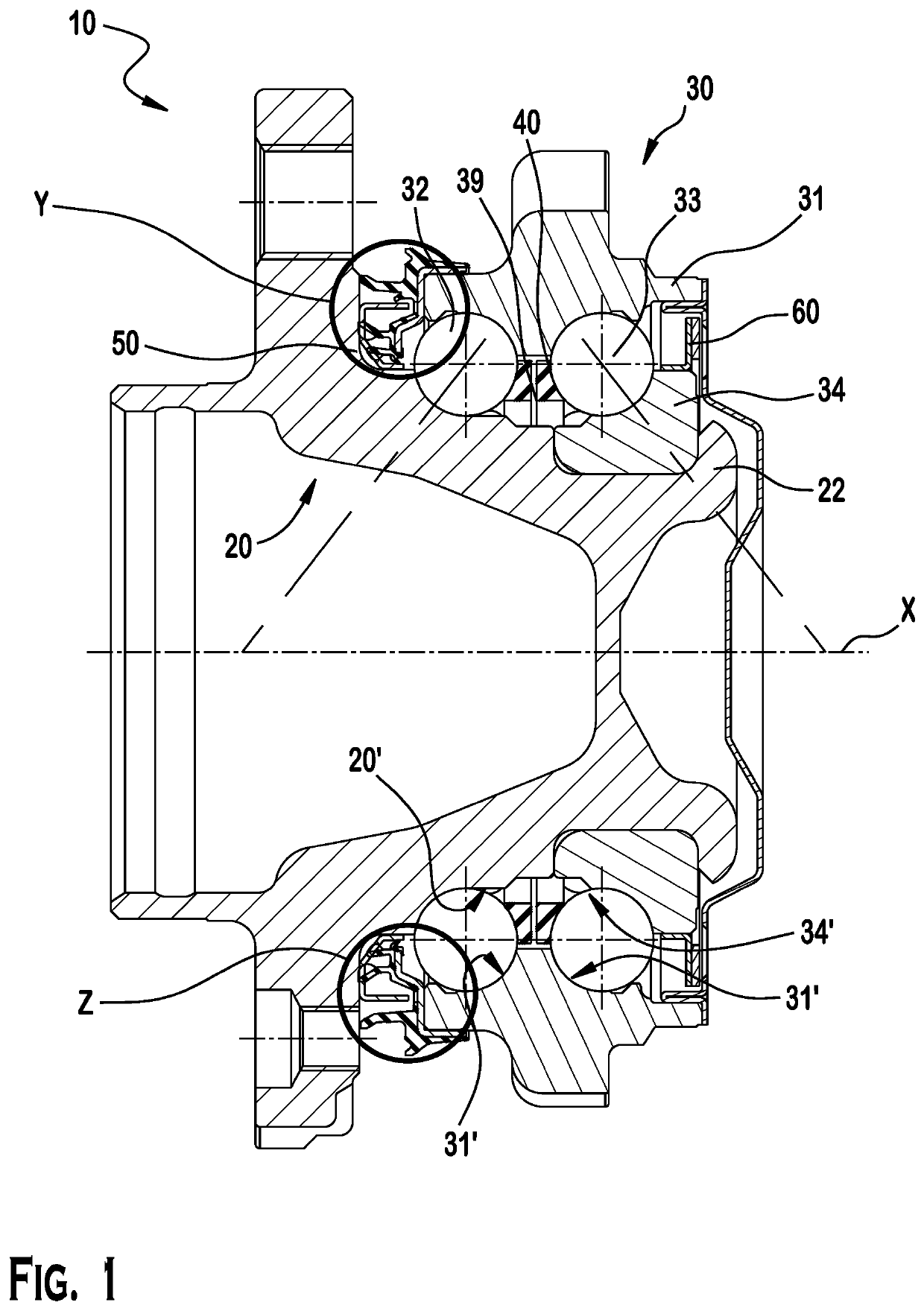
[0022]With reference to FIG. 1, a wheel hub assembly according to a preferred embodiment of the invention is denoted overall by 10. The figure shows a detail of the configuration provided by way of example.

[0023]The assembly 10 has a central rotation axis X and comprises a hub 20 which is rotating and a bearing unit 30 in turn comprising:

[0024]a stationary radially outer ring 31;

[0025]a radially inner ring 22 defined by the hub 20;

[0026]a further, rotating, radially inner ring 34 mounted on and integral with the hub 20;

[0027]two rows of rolling bodies 32, 33, in this example balls, arranged between the radially outer ring 31 and the radially inner rings 22 and 34; and

[0028]two cages 39 and 40 for keeping in position the rolling bodies of the rows of...


PUM


Abstract

A sealing device for a bearing unit having an axis of rotation and providing; a static component placed on a non-rotatable outer ring having a reinforcement support that abuts the outer ring and elastomeric material disposed on the reinforcement support, the elastomeric material forming first and second lips; a rigid shield configured for placement on one of a rotatable hub and a rotatable inner ring; the first and second lips have an equilibrium position where they do not contact the metallic shield; the elastomeric material forming a third lip that contacts the rigid shield to form an internal volume of the sealing device, the second lip and the rigid shield define a labyrinth seal in communication with the internal volume; the second lip, does not extend a full three hundred sixty degrees around the axis of rotation. This creates a channel for drainage of contaminants from the internal volume.

Description

CROSS-REFERENCE TO RELATED APPLICATIONS[0001]This application claims priority to Italian Patent Application no. 102019000005776, filed Apr. 16, 2019, the contents of which are fully incorporated herein by reference.TECHNICAL FIELD OF THE INVENTION[0002]The present invention relates to a cassette sealing device having innovative features which allow improved drainage therefrom of the contaminants which have penetrated inside the sealing device. Such a sealing device is applied to a bearing unit. The present invention is suitable in particular, although not exclusively, for the wheel hub assemblies of motor vehicles, the assemblies being provided with a bearing unit. More particularly, the bearing units according to the invention are those in which the outer ring of the bearing is stationary, while the inner ring of the bearing is rotatable. This invention is applicable, advantageously but not exclusively, to a bearing unit having a double row of balls.BACKGROUND OF THE INVENTION[0003...

Claims


Application Information

Patent Timeline
Patent Type & Authority Patents(United States)
IPC IPC(8): F16C33/78B60B27/00F16C33/72F16C33/80F16C19/08F16C19/18
CPCF16C33/7823B60B27/0073F16C33/726F16C33/805F16C19/08F16C19/186F16C2326/02F16C33/80F16C33/7886F16C2240/30F16J15/3264F16J15/3456F16J15/4476
Inventor NASTASI, ANTONIAA RE, PAOLO
Owner AB SKF
Why Eureka
Try Eureka