Magnetoresistance effect element including a crystallized Heusler alloy
a technology of magnetoresistance and effect elements, applied in the manufacture of flux-sensitive heads, instruments, record information storage, etc., can solve the problem of inability to obtain a large mr ratio easily, and achieve the effect of large mr ratio
- Summary
- Abstract
- Description
- Claims
- Application Information
AI Technical Summary
Benefits of technology
Problems solved by technology
Method used
Image
Examples
first embodiment
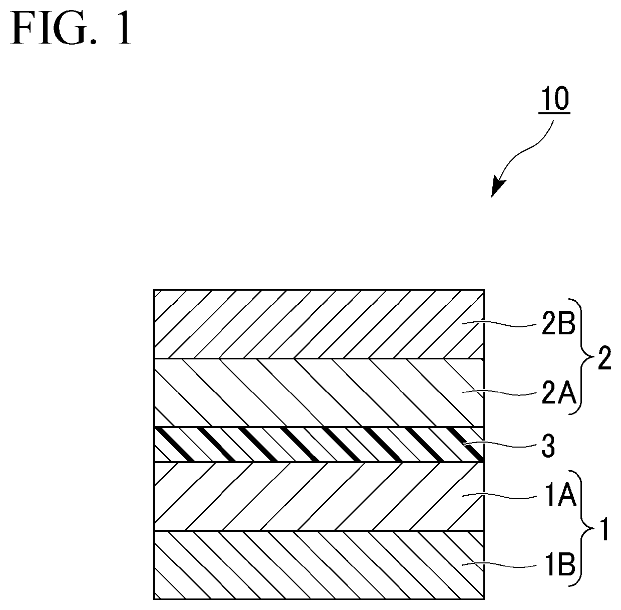
[0034]FIG. 1 is a cross-sectional view of a magnetoresistance effect element according to a first embodiment. First, directions will be defined. A direction in which the respective layers are laminated on each other is referred to as a lamination direction. Further, a direction intersecting the lamination direction in which each layer extends is referred to as an in-plane direction.
[0035]A magnetoresistance effect element 10 shown in FIG. 1 includes a first ferromagnetic layer 1, a second ferromagnetic layer 2, and a non-magnetic layer 3. The non-magnetic layer 3 is located between the first ferromagnetic layer 1 and the second ferromagnetic layer 2.
[0036]The magnetoresistance effect element 10 outputs a change in the relative angle between the magnetization of the first ferromagnetic layer 1 and the magnetization of the second ferromagnetic layer 2 as a change in the resistance value. The magnetization of the second ferromagnetic layer 2 is easier to move than, for example, the mag...
example 1
[0117]The magnetoresistance effect element 10 shown in FIG. 1 was manufactured as Example 1. The first ferromagnetic layer 1 and the second ferromagnetic layer 2 respectively include the first layers 1A and 2A and the second layers 1B and 2B. The first layers 1A and 2A were crystallized Co-based Heusler alloys and the compositional proportion was Co2FeGa0.5Ge0.5. The second layers 1B and 2B were crystallized CoFeB-A and the compositional proportion was (Co0.4Fe0.4B0.2)0.9Ta0.1. The non-magnetic layer 3 was Ag.
[0118]The magnetoresistance effect element 10 according to Example 1 was manufactured as below. First, the second layer 1B, the first layer 1A, the non-magnetic layer 3, the first layer 2A, and the second layer 2B having the above-described composition were formed on an amorphous substrate in this order by a sputtering method. At the time after the film formation, the first layers 1A and 2A were crystals with low crystallinity and the second layers 1B and 2B were amorphous.
[011...
example 2
[0124]Example 2 is different from Example 1 in that the composition of the first layers 1A and 2A is Co2FeGa0.6Ge0.8. In the Co-based Heusler alloy constituting the first layers 1A and 2A according to Example 2, the Co compositional proportion is smaller than that of the stoichiometric composition.
[0125]The MR ratio of the magnetoresistance effect element 10 according to Example 2 was 14% and RA was 0.09 Ω·μm2.
PUM
| Property | Measurement | Unit |
|---|---|---|
| thickness | aaaaa | aaaaa |
| thickness | aaaaa | aaaaa |
| thickness | aaaaa | aaaaa |
Abstract
Description
Claims
Application Information
 - R&D
- Intellectual Property
- Life Sciences
- Materials
- Tech Scout
- Unparalleled Data Quality
- Higher Quality Content
- 60% Fewer Hallucinations
Browse by: Latest US Patents, China's latest patents, Technical Efficacy Thesaurus, Application Domain, Technology Topic, Popular Technical Reports.
© 2025 PatSnap. All rights reserved.Legal|Privacy policy|Modern Slavery Act Transparency Statement|Sitemap|About US| Contact US: help@patsnap.com


