
Magnetoresistance effect element

a technology of magnetic effect and element, applied in the field of magnetic effect element, can solve the problem of inability to obtain a large mr ratio easily, and achieve the effect of large mr ratio

Active Publication Date: 2021-06-24
TDK CORPARATION
View PDF0 Cites 0 Cited by
  • Summary
  • Abstract
  • Description
  • Claims
  • Application Information

AI Technical Summary

Benefits of technology

The present invention is for a magnetoresistance effect element that has a high MR ratio. This means that it can detect small changes in magnetic field with a high degree of accuracy. As a result, it can be used in various applications such as magnetic field sensors and magnetic data storage devices.

Problems solved by technology

In the magnetoresistance effect element described in Patent Document 1, the ferromagnetic layer in contact with the non-magnetic layer is amorphous and a sufficiently large MR ratio cannot be easily obtained.

Method used


Image

  • Magnetoresistance effect element
  • Magnetoresistance effect element
  • Magnetoresistance effect element

Examples


first embodiment

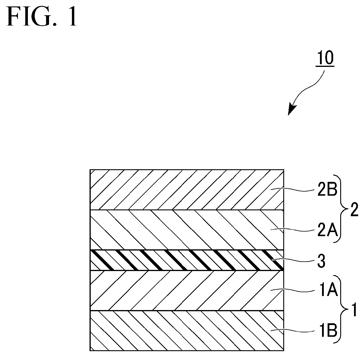
[0034]FIG. 1 is a cross-sectional view of a magnetoresistance effect element according to a first embodiment. First, directions will be defined. A direction in which the respective layers are laminated on each other is referred to as a lamination direction. Further, a direction intersecting the lamination direction in which each layer extends is referred to as an in-plane direction.

[0035]A magnetoresistance effect element 10 shown in FIG. 1 includes a first ferromagnetic layer 1, a second ferromagnetic layer 2, and a non-magnetic layer 3. The non-magnetic layer 3 is located between the first ferromagnetic layer 1 and the second ferromagnetic layer 2.

[0036]The magnetoresistance effect element 10 outputs a change in the relative angle between the magnetization of the first ferromagnetic layer 1 and the magnetization of the second ferromagnetic layer 2 as a change in the resistance value. The magnetization of the second ferromagnetic layer 2 is easier to move than, for example, the mag...

example 1

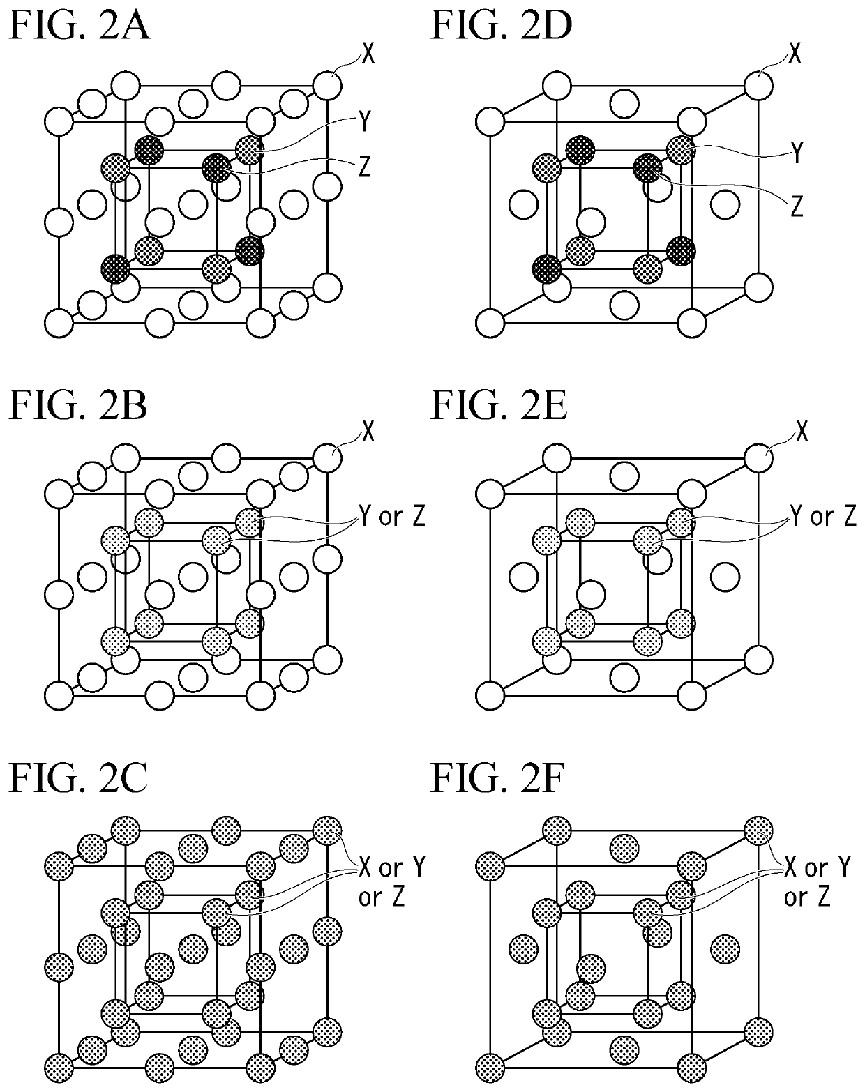
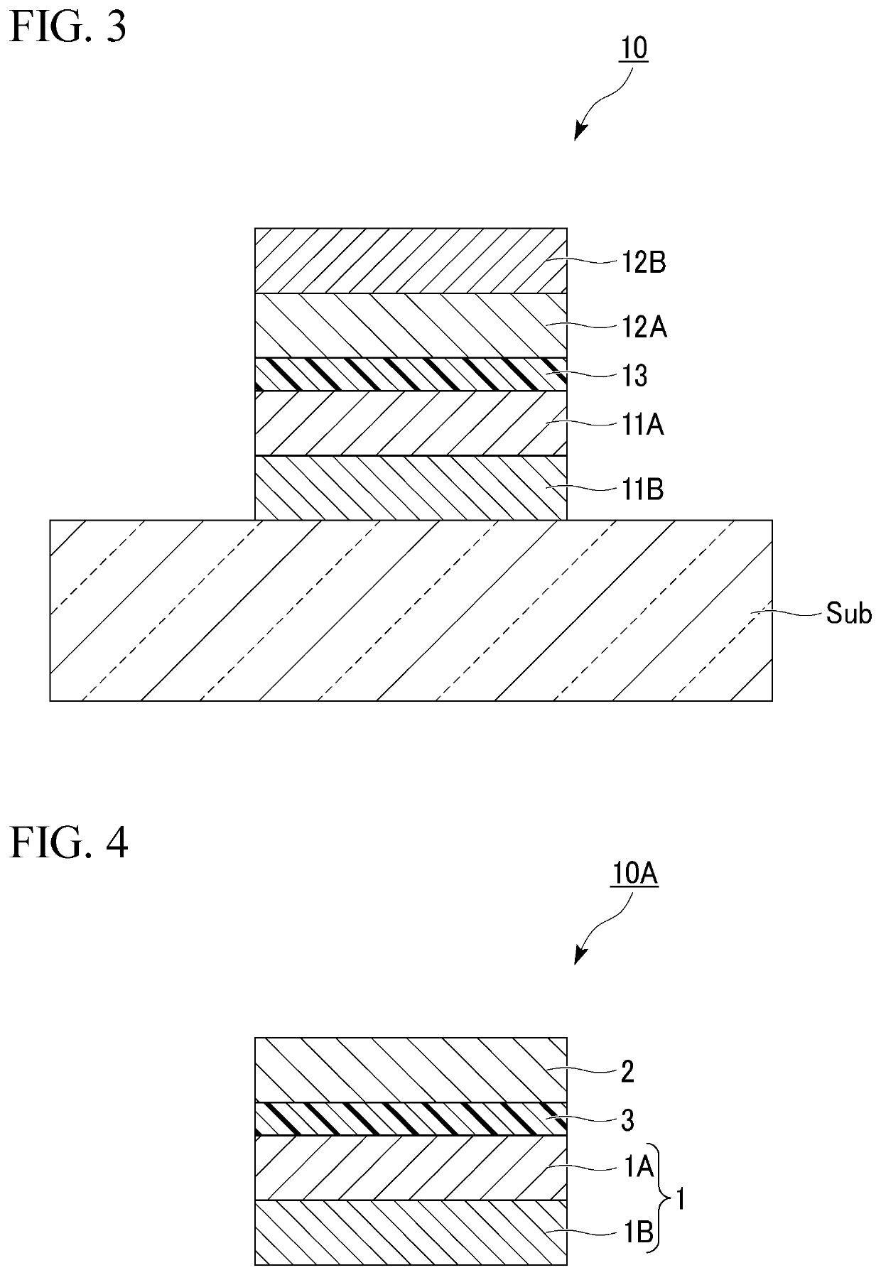
[0117]The magnetoresistance effect element 10 shown in FIG. 1 was manufactured as Example 1. The first ferromagnetic layer 1 and the second ferromagnetic layer 2 respectively include the first layers 1A and 2A and the second layers 1B and 2B. The first layers 1A and 2A were crystallized Co-based Heusler alloys and the compositional proportion was Co2FeGa0.5Ge0.5. The second layers 1B and 2B were crystallized CoFeB-A and the compositional proportion was (Co0.4Fe0.4B0.2)0.9Ta0.1. The non-magnetic layer 3 was Ag.

[0118]The magnetoresistance effect element 10 according to Example 1 was manufactured as below. First, the second layer 1B, the first layer 1A, the non-magnetic layer 3, the first layer 2A, and the second layer 2B having the above-described composition were formed on an amorphous substrate in this order by a sputtering method. At the time after the film formation, the first layers 1A and 2A were crystals with low crystallinity and the second layers 1B and 2B were amorphous.

[011...

example 2

[0124]Example 2 is different from Example 1 in that the composition of the first layers 1A and 2A is Co2FeGa0.6Ge0.8. In the Co-based Heusler alloy constituting the first layers 1A and 2A according to Example 2, the Co compositional proportion is smaller than that of the stoichiometric composition.

[0125]The MR ratio of the magnetoresistance effect element 10 according to Example 2 was 14% and RA was 0.09 Ω·μm2.


PUM

PropertyMeasurementUnit
thicknessaaaaaaaaaa
thicknessaaaaaaaaaa
thicknessaaaaaaaaaa

Abstract

A magnetoresistance effect element includes: a first ferromagnetic layer; a second ferromagnetic layer; and a non-magnetic layer provided between the first ferromagnetic layer and the second ferromagnetic layer, wherein at least one of the first ferromagnetic layer and the second ferromagnetic layer includes a first layer and a second layer in order from the side closer to the non-magnetic layer, the first layer contains a crystallized Co-based Heusler alloy, at least a part of the second layer is crystallized, the second layer contains a ferromagnetic element, boron element and an additive element, and the additive element is any element selected from a group consisting of Ti, V, Cr, Cu, Zn, Zr, Mo, Ru, Pd, Ta, W, Ir, Pt, and Au.

Description

BACKGROUND OF THE INVENTIONField of the Invention[0001]The present invention relates to a magnetoresistance effect element.Description of Related Art[0002]A magnetoresistance effect element is an element of which a resistance value in a lamination direction changes due to a magnetoresistance effect. The magnetoresistance effect element includes two ferromagnetic layers and a non-magnetic layer sandwiched therebetween. A magnetoresistance effect element in which a conductor is used for the non-magnetic layer is called as a giant magnetoresistance effect (GMR) element and a magnetoresistance effect element in which an insulating layer (a tunnel barrier layer or a barrier layer) is used for the non-magnetic layer is called a tunneling magnetoresistance effect (TMR) element. Magnetoresistance effect elements can be applied to various applications such as a magnetic sensor, a radio frequency component, a magnetic head, and a non-volatile random access memory (MRAM).[0003]Patent Document ...

Claims


Application Information

Patent Timeline
Patent Type & Authority Applications(United States)
IPC IPC(8): H01L43/08H01L43/04H01L43/10G11C11/16G11B5/39G01R33/09H10N50/10H10N50/80H10N52/80
CPCH01L43/08H01L43/04G01R33/093G11C11/161G11B5/3909H01L43/10H10N50/80H10N50/85H10N50/10G01R33/098G11C11/1675G11C11/1673G11C11/1659H03B15/006G01R33/091G11B5/3906G11B5/3903H10N52/80
Inventor ICHIKAWA, SHINTOINUBUSHI, KAZUUMINAKADA, KATSUYUKI
Owner TDK CORPARATION
Learn More