
Magnetoresistive effect element and crystallization method of ferromagnetic layer

A technology of magnetoresistive effect element and ferromagnetic layer, which is applied in the direction of electrical components, parts of electromagnetic equipment, and resistors controlled by magnetic field, and can solve the problem of large output of magnetic sensors

Active Publication Date: 2021-12-03
TDK CORPARATION
View PDF11 Cites 0 Cited by
  • Summary
  • Abstract
  • Description
  • Claims
  • Application Information

AI Technical Summary

Problems solved by technology

According to Patent Document 1, the output of the magnetic sensor increases by making the ferromagnetic layer a laminated structure of an amorphous layer and a crystalline layer.

Method used


Image

  • Magnetoresistive effect element and crystallization method of ferromagnetic layer
  • Magnetoresistive effect element and crystallization method of ferromagnetic layer
  • Magnetoresistive effect element and crystallization method of ferromagnetic layer

Examples


no. 1 approach ”

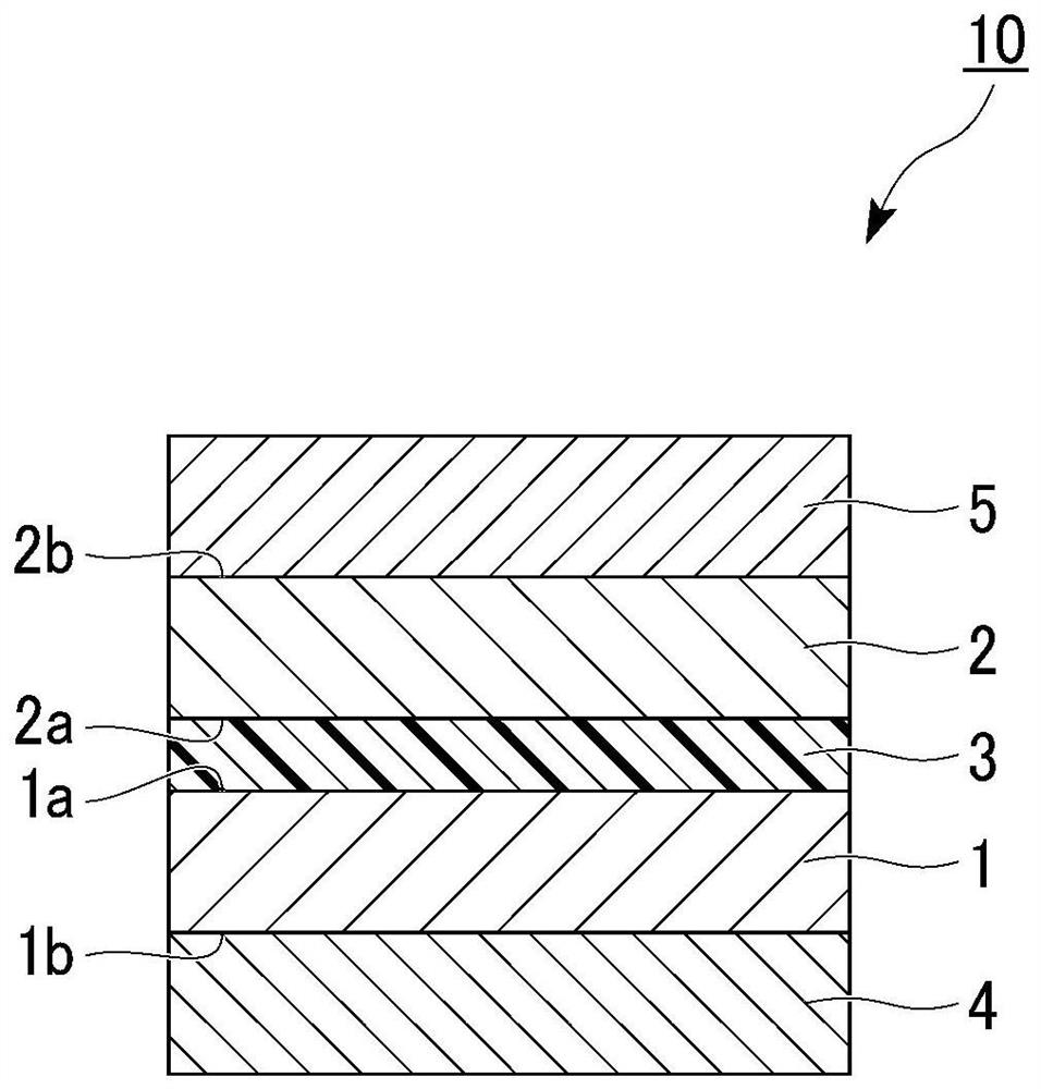
[0039] figure 1 It is a cross-sectional view of the magnetoresistive effect element of the first embodiment. First, define the direction. The direction in which the respective layers are stacked is sometimes referred to as the stacking direction. In addition, the direction intersecting with the stacking direction and extending each layer may be referred to as an in-plane direction.

[0040] figure 1 The magnetoresistance effect element 10 shown includes a first ferromagnetic layer 1 , a second ferromagnetic layer 2 , a nonmagnetic layer 3 and additive-containing layers 4 , 5 . The non-magnetic layer 3 is located between the first ferromagnetic layer 1 and the second ferromagnetic layer 2 . The additive-containing layers 4, 5 sandwich the first ferromagnetic layer 1, the nonmagnetic layer 3, and the second ferromagnetic layer 2 in the stacking direction.

[0041] The magnetoresistance effect element 10 outputs a change in the relative angle between the magnetization of the...


PUM

PropertyMeasurementUnit
thicknessaaaaaaaaaa

Abstract

The invention discloses a magnetoresistive effect element (10), and the magnetoresistive effect element (10) includes a first ferromagnetic layer (1), a second ferromagnetic layer (2), a non-magnetic layer (3) disposed between the first ferromagnetic layer (1) and the second ferromagnetic layer (3), and an additive-containing layer (4, 5) disposed at any position in a laminating direction, at least one of the first ferromagnetic layer and the second ferromagnetic layer is a Heusler alloy containing at least one of boron and carbon, at least part of which is crystallized, and the additive-containing layer is a non-magnetic layer containing at least one of boron and carbon, and any one element selected from the group made of Ti, V, Cr, Cu, Zn, Zr, Mo, Ru, Pd, Ta, W, Ir, Pt and Au.

Description

technical field [0001] The present invention relates to a crystallization method of a magnetoresistance effect element and a ferromagnetic layer. Background technique [0002] The magnetoresistance effect element is an element whose resistance value in the stacking direction changes due to the magnetoresistance effect. A magnetoresistance effect element includes two ferromagnetic layers and a nonmagnetic layer sandwiched between them. A magnetoresistance effect element that uses a conductor for the nonmagnetic layer is called a giant magnetoresistance (GMR) element, and a magnetoresistance effect element that uses an insulating layer (tunnel barrier layer, barrier layer) for the nonmagnetic layer is called a tunnel magnetoresistance (TMR) element. )element. Magnetoresistive effect elements can be applied to various purposes such as magnetic sensors, high-frequency components, magnetic heads, and nonvolatile random access memories (MRAM). [0003] Patent Document 1 disclos...

Claims


Application Information

Patent Timeline
Patent Type & Authority Applications(China)
IPC IPC(8): H01L43/10H01F10/26H01L21/8239H01L27/105H01L43/08H10N50/01H10N50/10H10N50/80
CPCH01F10/26G11C11/1675G11C11/161G11B5/3906H10N50/85H10N50/10H10N50/01H10N50/80
Inventor 市川心人犬伏和海中田胜之
Owner TDK CORPARATION
Learn More