
Method for manufacturing magnetic field detecting element, utilizing diffusion of metal

a magnetic field and detecting element technology, applied in the field of magnetic field detecting elements, can solve the problem of limited magnetic striction at the boundary, and achieve the effect of low magnetic striction and large mr ratio

Active Publication Date: 2010-03-02
TDK CORPARATION
View PDF17 Cites 10 Cited by
  • Summary
  • Abstract
  • Description
  • Claims
  • Application Information

AI Technical Summary

Benefits of technology

The present invention provides a magnetic field detecting element for a CPP-GMR head with low magneto striction and potential for a large MR ratio. The element includes a free layer, a pinned layer, and a non-magnetic spacer layer. The manufacturing method involves depositing layers in a specific order and heat treating them to form the free layer. The element has a reduced magneto striction at the boundary between the spacer adjoining layer and the Heusler alloy layer, which is facilitated by the structure of the spacer adjoining layer and the Heusler alloy layer. The element can be used in a slider for a hard disk drive. The technical effects of the invention are improved performance and reliability of the CPP-GMR head.

Problems solved by technology

The inventors think that the spacer adjoining layer having the body centered cubic structure better matches the Heusler alloy layer with regard to the crystal structure, and does not provide as good a match with the metal layer, and therefore, that the metal layer is diffused toward the spacer adjoining layer without being impeded by lattice structure, and as a result, that magneto striction at the boundary is limited.

Method used


Image

  • Method for manufacturing magnetic field detecting element, utilizing diffusion of metal
  • Method for manufacturing magnetic field detecting element, utilizing diffusion of metal
  • Method for manufacturing magnetic field detecting element, utilizing diffusion of metal

Examples


experiment 1

(Experiment 1)

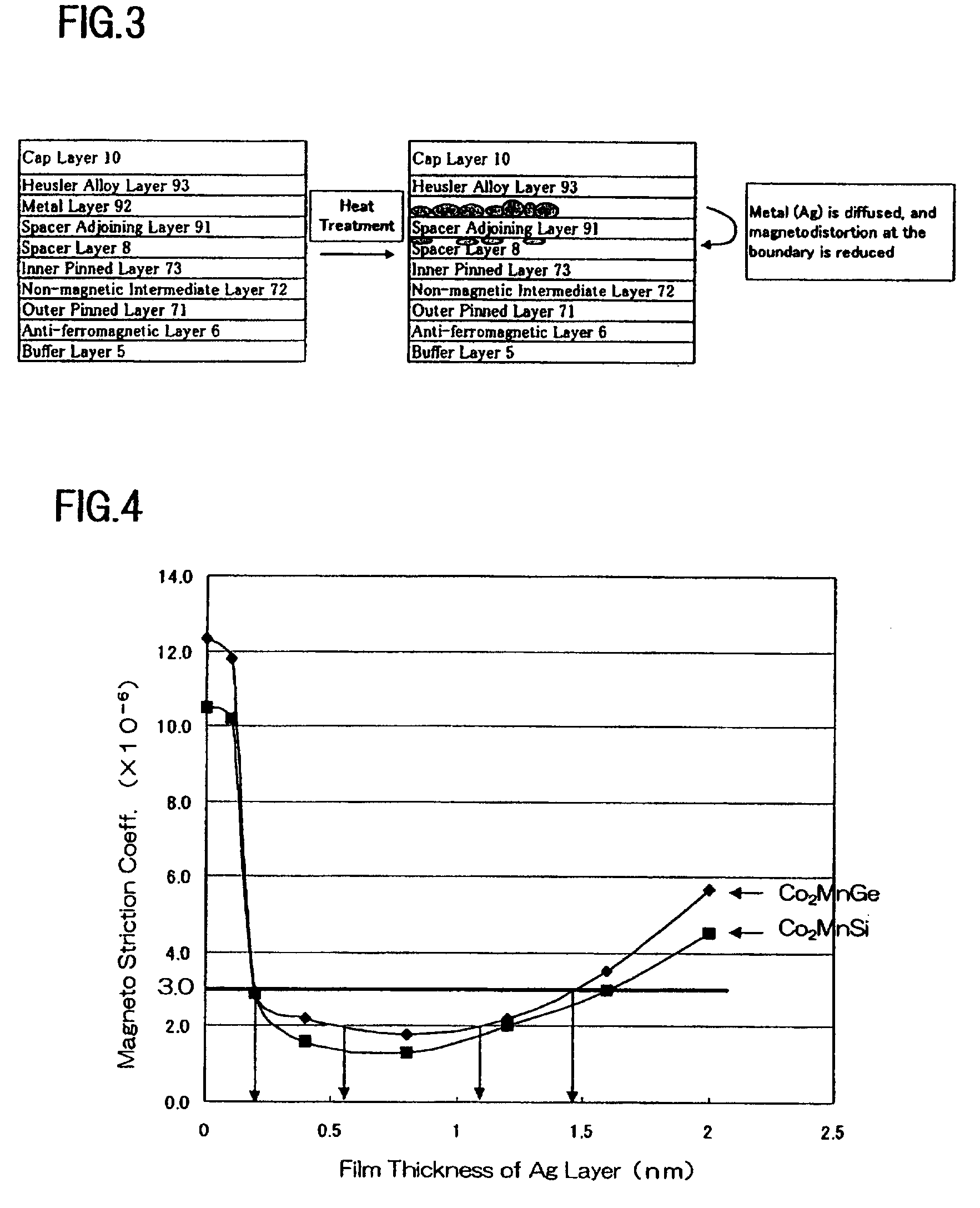
[0049]First, influence of the thickness of metal layer 92 on magneto striction and the MR ratio were investigated. Silver was used for metal layer 92. Co2MnSi and Co2MnGe were used for Heusler alloy metal 93, and CoFe was used for spacer adjoining layer 91. As shown in Table 3 and FIG. 4, the magneto striction coefficient was limited to less than +3×10⁻⁶ by inserting a silver layer having a thickness of approximately 0.2 nm or more, whereas the magneto striction coefficient exceeded +10×10−6 when a silver layer was not provided. The inventors think that this is because magneto striction is reduced at the boundary between spacer adjoining layer 9 and Heusler alloy layer 93 because of the effect of inserting a silver layer, as mentioned above. However, the magneto striction coefficient was found to be increased again when the thickness was further increased. This is because a large amount of silver remains in the silver layer due to excessive thickness of the silver laye...

experiment 2

(Experiment 2)

[0051]An experiment that is similar to Experiment 1 was conducted using gold for metal layer 92. As shown in Table 4 and FIG. 5, the magneto striction coefficient was more than +10×10−6 when a gold layer was not provided. However, the magneto striction coefficient was less than +3×10⁻⁶ when a gold layer having a thickness of approximately 0.2 nm or more was inserted. However, as the thickness was further increased, the magneto striction coefficient was found to be increased again. In this way, the general tendency was similar to the case in which silver was used. In order to achieve magneto striction coefficient that is no more than 3×10⁻⁶ in the case of Co2MnSi and Co2MnGe, the thickness of the gold layer has to be equal to or more than 0.2 nm and equal to or less than 1.4 nm. Further, in order to achieve a magneto striction coefficient that is no more than 2×10⁻⁶, the thickness of the gold layer has to be equal to or more than 0.3 nm and equal to or less than 1.1 nm....

experiment 3

(Experiment 3)

[0053]Although 70CoFe was used for spacer adjoining layer 91 in Experiments 1 and 2, the influence of the composition of CoFe on the magneto striation coefficient was evaluated by varying the composition of CoFe as a parameter in this experiment. Silver was used for metal layer 92, and gold was also used in some cases. The thickness of the silver layer was evaluated in three cases, i.e., 0 nm (silver was not provided), 0.4 nm, and 0.8 nm. In each case, the atomic percent of Co was varied from 70% to 90% in increments of 5%. Investigations were also conducted for some cases in which the Heusler alloy layer was made of Co2MnGe, and for a case in which the thickness of the silver layer was 1.2 nm. Table 5 and FIGS. 6, 7 show the result of Experiment 3. FIG. 6 is a graph showing the magneto striction coefficient in relation to the atomic percent of Co, which is shown in the horizontal axis, when metal layer 92 was made of a silver layer having a thickness of 0 to 0.8 nm, a...


PUM

PropertyMeasurementUnit
thicknessaaaaaaaaaa
thicknessaaaaaaaaaa
thicknessaaaaaaaaaa

Abstract

A method for manufacturing a magnetic field detecting element has the steps of: forming stacked layers by sequentially depositing a pinned layer, a spacer layer, a spacer adjoining layer which is adjacent to the spacer layer, a metal layer, and a Heusler alloy layer in this order, such that the layers adjoin each other; and heat treating the stacked layers in order to form the free layer out of the spacer adjoining layer, the metal layer, and the Heusler alloy layer. The spacer adjoining layer is mainly formed of cobalt and iron, and has a body centered cubic structure, and the metal layer is formed of an element selected from the group consisting of silver, gold, copper, palladium, or platinum, or is formed of an alloy thereof.

Description

[0001]This Application is a U.S. Utility Patent Application which claims foreign priority from Japanese Application No. 2006-164574, filed Jun. 14, 2006, the complete disclosure of which is incorporated herein by reference.BACKGROUND OF THE INVENTION[0002]1. Field of the Invention[0003]The present invention relates to a magnetic field detecting element which is used in a hard disk drive, and particularly to a method for manufacturing a magnetic field detecting element.[0004]2. Description of the Related Art[0005]A spin-valve type GMR (Giant Magneto-Resistive) head is known as a magnetic head which meets requirements for high sensitivity and high output. A magnetic field detecting element that is used in a spin-valve type GMR head has a free layer and a pinned layer. These layers are stacked with a non-magnetic spacer layer interposed therebetween. The free layer is made of a ferromagnetic material, and the magnetization direction changes in accordance with an external magnetic field...

Claims


Application Information

Patent Timeline
Patent Type & Authority Patents(United States)
IPC IPC(8): G11B5/127
CPCB82Y25/00G01R33/093G11B5/3906H01L43/12G11B5/3163Y10T428/1121H10N50/01
Inventor TSUCHIYA, YOSHIHIROMIZUNO, TOMOHITOHIRATA, KEIKAWAMORI, KEITASHIMAZAWA, KOJI
Owner TDK CORPARATION
Learn More