Check patentability & draft patents in minutes with Patsnap Eureka AI!

Catch fence system

a technology of catch fences and fences, which is applied in the field of catch fences, can solve the problems of driver fatalities and serious injuries, drivers may be able to lift off the racetrack and impact the catch fence, and the current catch fence design has not been optimized to minimize the injury of drivers,

Active Publication Date: 2021-11-02
BROCK TERRY
View PDF21 Cites 0 Cited by
  • Summary
  • Abstract
  • Description
  • Claims
  • Application Information

AI Technical Summary

Benefits of technology

The catch fence system effectively absorbs and redirects the energy of impacting cars, reducing the risk of injury to drivers and spectators by tilting frame members and using sliding cables with stop blocks to manage the force of impact, enhancing safety without altering the spectator experience.

Problems solved by technology

The cars involved in the crash may also elevate off the racetrack and impact the catch fence.
Unfortunately, current catch fence designs have not been optimized to minimize injury to drivers.
Consequently, there have been fatalities and serious injuries to drivers when they impact the catch fences in motorsports.
In addition, there have been injuries to fans as well.
They are a threat to the safety of the driver and the fans when they are impacted.
The design of current catch fences, however, have deficiencies.
This design contains the car and protects the fans, but the fans are not protected if a car is destroyed in front of them.

Method used


Image

  • Catch fence system
  • Catch fence system
  • Catch fence system

Examples


Embodiment Construction

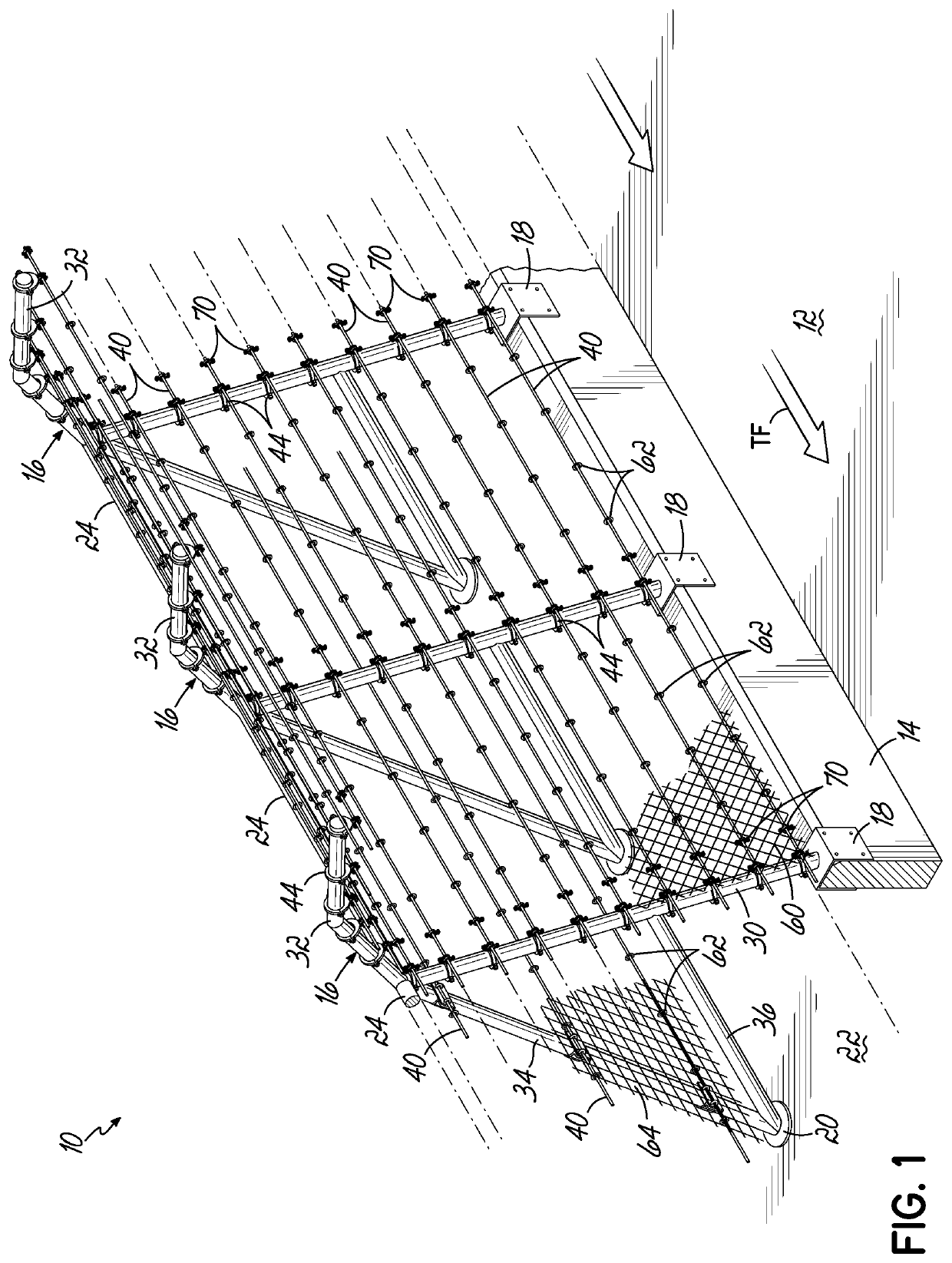
[0036]A section of a catch fence system 10 constructed in accordance with an embodiment of the invention as illustrated in FIG. 1. The catch fence system 10 provides a safer catch fence for drivers without altering the experience of the spectators. The catch fence system may be utilized for high-speed race tracks, road courses, or temporary street course. In one exemplary setting, the catch fence system 10 may be used to encircle the entire outer boundary of a race track such that there are no breaks in the catch fence system 10. In another exemplary setting, only a portion of the catch fence system 10 may be used for protection, for example, a short section of a road course such as the type used for grand prix races through city streets. In yet another setting, the catch fence system 10 may be used on a public highway or roadway, including temporary barriers.

[0037]Unless stated otherwise, the description of the catch fence system 10 below will be based on the catch fence system 10 ...


PUM


Abstract

A catch fence system for use at a race track having a retaining wall. The catch fence system includes first and second frame members with each having a lower front member with a mounting bracket adapted to connect the lower front member to the retaining wall. A first support ring is affixed to the lower front member of the first frame member and a second support ring is affixed to the lower front member of the second frame member. A first front cable extends through the first and second support rings. A first stop block is affixed to first front cable to the outside of and a distance L1 from the first support ring and a second stop block is affixed to the first front cable to the outside of and a distance L2 from the second support ring, wherein the distance L2 is greater than the distance L1.

Description

CROSS-REFERENCE TO RELATED APPLICATIONS[0001]The present application claims priority to U.S. Provisional Patent Application No. 62 / 792,520 filed Jan. 15, 2019, the disclosure of which is hereby incorporated herein by reference in its entirety.FIELD OF THE INVENTION[0002]The invention relates generally to catch fences for motorsports.BACKGROUND OF THE INVENTION[0003]Auto racing often involves crashes of one or more cars. Under certain circumstances, cars involved in the crash will strike the concrete retaining wall circling the outer part of the racetrack. To minimize injuries to drivers impacting the solid concrete wall, a safer barrier was developed and installed on retaining walls at the Indianapolis Motor Speedway in 2002. Since then there have been no fatalities or serious injuries associated with safer barrier impacts.[0004]The cars involved in the crash may also elevate off the racetrack and impact the catch fence. Unfortunately, current catch fence designs have not been optim...

Claims


Application Information

Patent Timeline
Patent Type & Authority Patents(United States)
IPC IPC(8): E04H17/08E01F15/14E04H17/10E01F15/06A63K3/00
CPCE04H17/08A63K3/00E01F15/06E01F15/146E04H17/10
Inventor BROCK, TERRY
Owner BROCK TERRY
Features
  • R&D
  • Intellectual Property
  • Life Sciences
  • Materials
  • Tech Scout
  • Unparalleled Data Quality
  • Higher Quality Content
  • 60% Fewer Hallucinations
Learn More