
Method and device comprising UV detectors for monitoring UV light exposure of a flat-ply of prepreg

a technology of prepreg and detector, which is applied in the direction of optical radiation measurement, instruments, wireless architecture use, etc., can solve the problems of undesired changes in the structure formed of certain materials, adversely affecting the performance of the structure made from these materials, and the characteristics of the prepreg used in the production of composite structures may not be optimal, so as to achieve the effect of avoiding complex and/or cumbersome equipment and total exposure of the structur

Active Publication Date: 2021-11-09
THE BOEING CO
View PDF9 Cites 0 Cited by
  • Summary
  • Abstract
  • Description
  • Claims
  • Application Information

AI Technical Summary

Benefits of technology

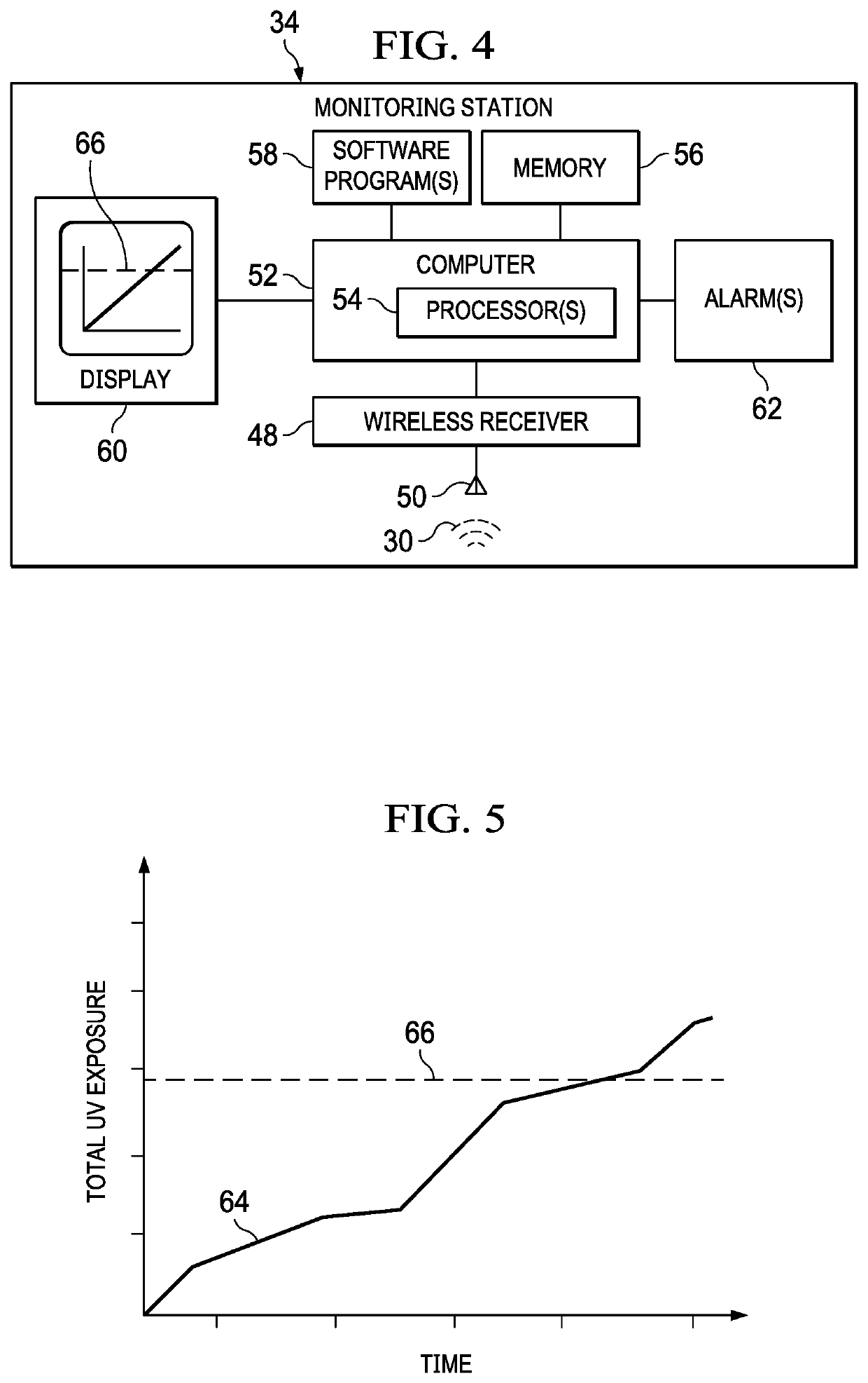
[0009]One of the advantages of the disclosed embodiments is that the total exposure of a structure to UV light can be determined inexpensively and avoids the need for complex and / or cumbersome equipment. The disclosed UV light detector and monitoring system solves the problem of determining whether a material such as a prepreg has been overexposed or underexposed to UV light. Another advantage of the disclosed embodiments is that specific areas of a structure can be monitored for UV light exposure. A further advantage is that UV light exposure of a structure can be remotely monitored. Still another advantage of the disclosed embodiments is that UV light exposure can be accumulated over time and compared to a threshold level. Still another advantage is that an alert can be automatically generated when the accumulated UV light exposure of a structure has exceeded a preselected level.

Problems solved by technology

Structures formed of certain materials may undergo undesired changes when subjected to UV (ultraviolet) light over a period of time.
Partial curing of the prepreg due to UV exposure may adversely affect the performance of structures made from these materials.
As result, prepregs used in production of composite structures may have less than optimal characteristics, or alternatively, prepreg materials may be prematurely discarded as a result of an overestimate of UV exposure.
In some cases, fully cured composite structures as well as structures made from other materials may also undergo undesired changes when overexposed to UV light.

Method used


Image

  • Method and device comprising UV detectors for monitoring UV light exposure of a flat-ply of prepreg
  • Method and device comprising UV detectors for monitoring UV light exposure of a flat-ply of prepreg
  • Method and device comprising UV detectors for monitoring UV light exposure of a flat-ply of prepreg

Examples


Embodiment Construction

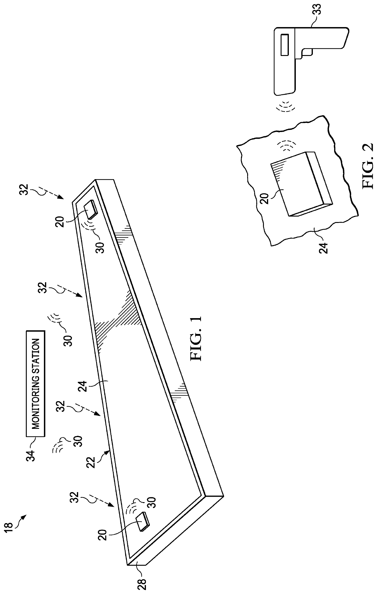
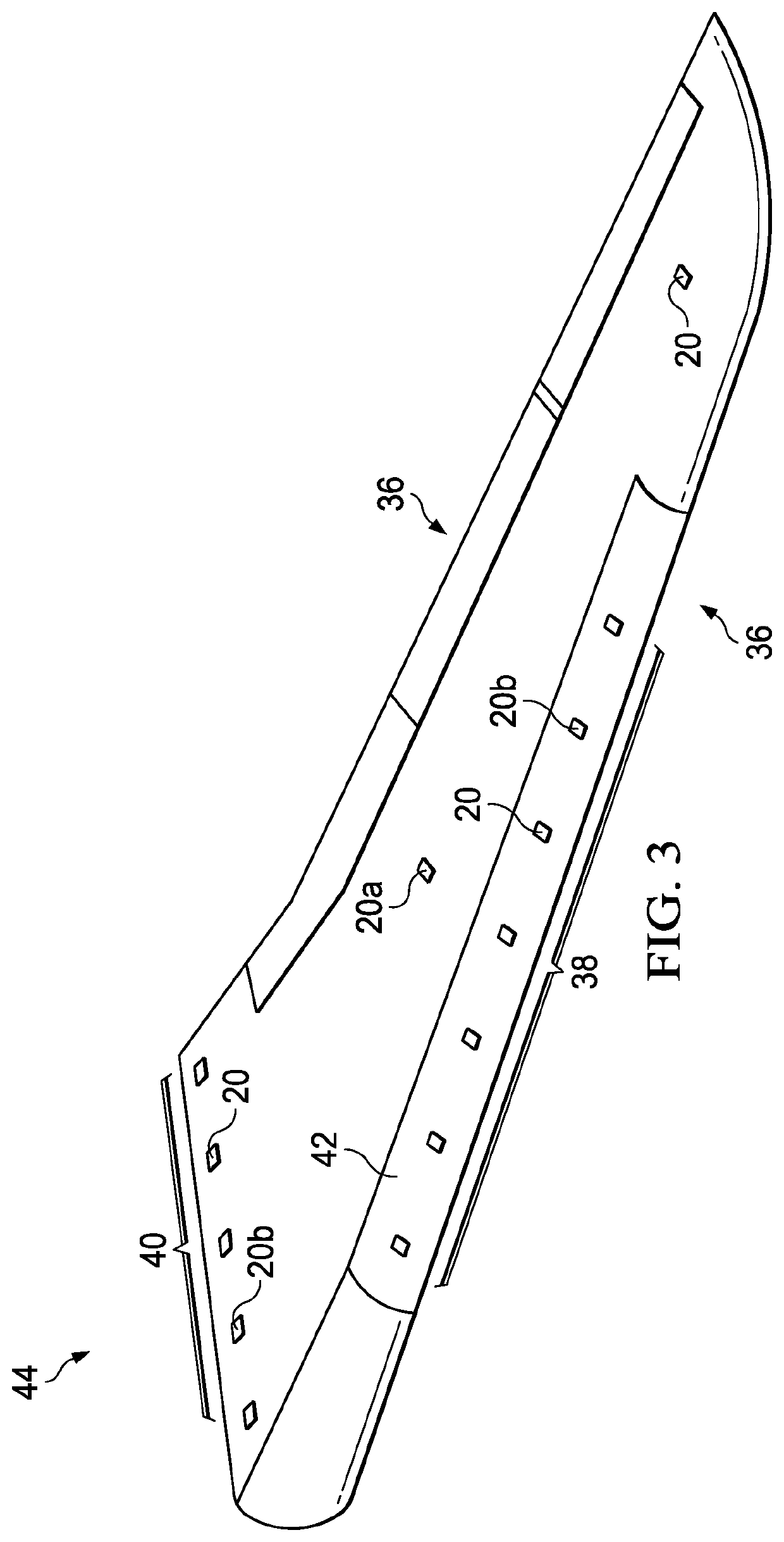
[0029]FIG. 1 illustrates a system 18 for detecting and accumulating the amount of UV light 32 incident on the surface 24 of a structure 22. The structure 22 may be a cured or uncured polymer, or other material whose characteristics or properties may be undesirably altered due to exposure to UV light 32 over a period of time. In the illustrated example, the structure 22 comprises a flat ply of prepreg supported on an underlying tool 28. However, the structure 22 may have any shape and may include contoured and / or irregular surfaces.

[0030]The system 18 includes one or more UV light detectors (hereinafter “UV detector”) 20 which are attached to the surface 24 of the structure 22 by any suitable technique. For example, the UV detector 20 may be removably attached to a structure 22 using an adhesive or similar attachment means, as will be discussed later in more detail. The UV detector 20 is flexible, thereby allowing it to conform to surface contours or irregularities on the structure 2...


PUM

PropertyMeasurementUnit
wavelengthsaaaaaaaaaa

Abstract

A UV detection device is removably attached to a surface of a structure and includes a photodetector to detect UV light incident on the structure. The UV detection device includes signal processing and a transmitter that wirelessly transmits UV detection data to a remote monitoring station where the detection signals are accumulated and analyzed to determine the total exposure of the structure to UV light.

Description

BACKGROUND INFORMATION1. Field[0001]The present disclosure generally relates to structures formed of materials that are subject to change when exposed to UV light and deals more particularly with a device and method for detecting and monitoring the amount of UV exposure of such structures.2. Background[0002]Structures formed of certain materials may undergo undesired changes when subjected to UV (ultraviolet) light over a period of time. For example, composite prepregs in which the matrix is only partially cured begin to undergo curing (polymerization) when exposed to room temperatures. Consequently, the prepreg is often placed in cold storage until ready for use. However, prepreg may begin to undergo at least partial curing when exposed to UV light. UV light affecting prepreg may originate from various sources, particularly in high-production environments, such as the sun, fluorescent lights, mercury lamps, hydrogen lamps, and xenon arc lamps, to name only a few.[0003]Partial curin...

Claims


Application Information

Patent Timeline
Patent Type & Authority Patents(United States)
IPC IPC(8): G01J1/42H04Q9/00G01J1/44
CPCG01J1/429H04Q9/00G01J2001/4413H04Q2209/40H04Q2209/886H04Q2209/47G08C17/02H04Q2209/88G01J1/0219G01J1/0403G01J1/0247G01J1/42
Inventor SAFAI, MORTEZA
Owner THE BOEING CO
Learn More