Systems and methods for controlling silica dust during hydraulic fracturing operations using an improved manifold

a hydraulic fracturing and manifold technology, applied in the field of hydraulic fracturing, can solve the problems of insufficient control of silica dust, significant safety challenges in transportation and unloading of frac sand, and ineffective techniques, etc., to improve the efficiency and flexibility of the frac sand offloading process, and improve the effect of worker tim

a hydraulic fracturing and manifold technology, applied in the field of hydraulic fracturing, can solve the problems of insufficient control of silica dust, significant safety challenges in transportation and unloading of frac sand, and ineffective techniques, etc., to improve the efficiency and flexibility of the frac sand offloading process, and improve the effect of worker tim

US11185900B2Active Publication Date: 2021-11-30SIERRA DUST CONTROL

Image

  • Systems and methods for controlling silica dust during hydraulic fracturing operations using an improved manifold
  • Systems and methods for controlling silica dust during hydraulic fracturing operations using an improved manifold
  • Systems and methods for controlling silica dust during hydraulic fracturing operations using an improved manifold

Examples


Embodiment Construction

[0051]The principles of the present invention and their advantages are best understood by referring to the illustrated embodiment depicted in FIGS. 1-9 of the drawings, in which like numbers designate like parts.

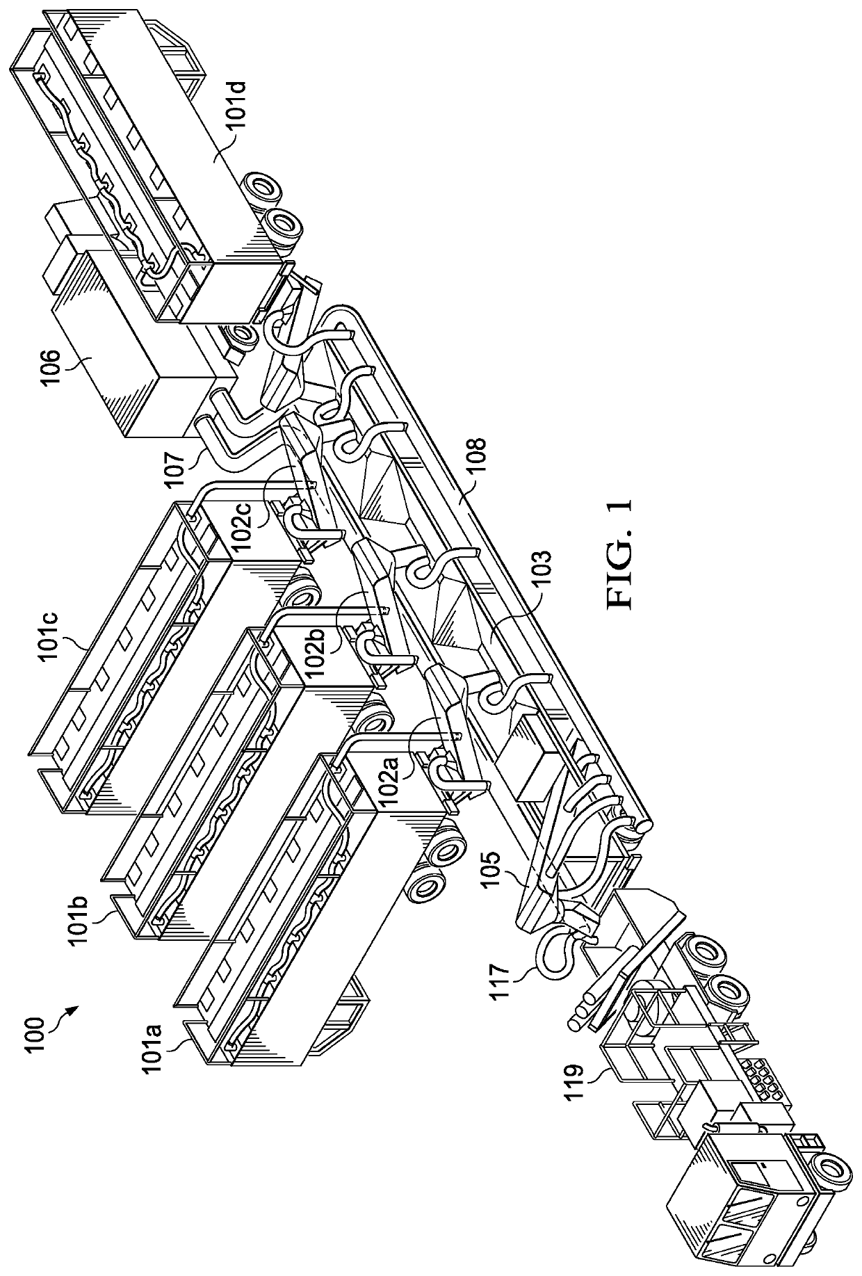
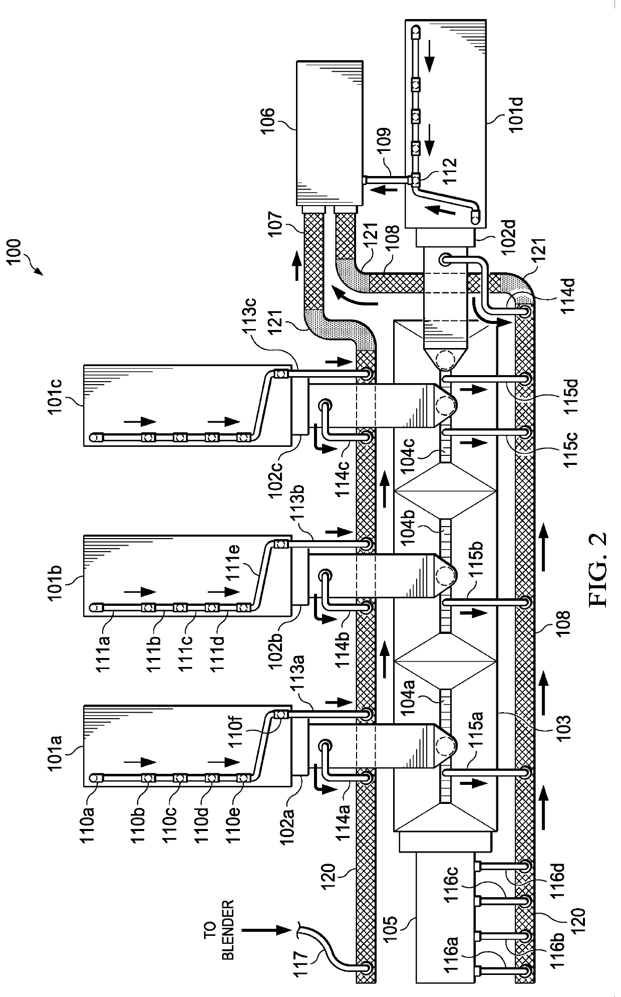
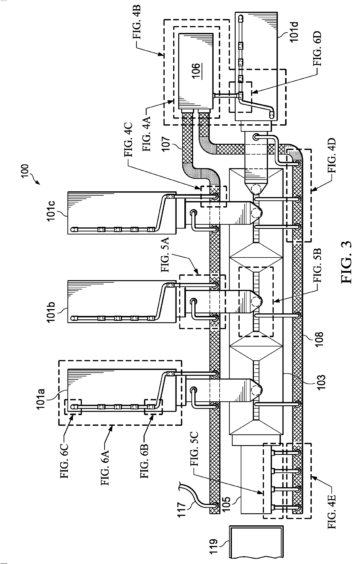
[0052]FIG. 1 is a diagram of an exemplary frac sand transportation, storage, and unloading system 100 including a frac sand silica dust control system according to a preferred embodiment of the principles of the present invention. System 100 is also shown in the plan views of FIGS. 2 and 3, with FIG. 2 emphasizing the air flow paths of the silica dust control system and FIG. 3 generally showing the locations of particular features of the silica dust control system shown in further detail in FIGS. 4-6.

[0053]Generally, system 100 is assembled at a hydraulic fracturing worksite and is used to offload frac sand transported to the worksite from a frac sand supplier via trailers and offloaded into a blender. The blender mixes the sand with the water and chemicals to form the fraci...


PUM


Abstract

A system for controlling dust during hydraulic fracturing operations includes a manifold having a plurality of ports for capturing dust when negative air pressure is applied to the manifold. A support frame positions the manifold above a piece of hydraulic fracturing equipment receiving sand from a sand source.

Description

CROSS-REFERENCE TO RELATED APPLICATIONS[0001]The present application is a continuation-in-part of U.S. patent Ser. No. 14 / 862,354, filed Sep. 23, 2015, which is a continuation of application Ser. No. 14 / 527,868, filed Oct. 30, 2014, which is a divisional of U.S. patent application Ser. No. 14 / 178,782, filed Feb. 12, 2014, which is a continuation of U.S. patent application Ser. No. 13 / 769,456, filed Feb. 18, 2013, all of which are incorporated herein by reference for all purposes.[0002]The present application also claims the benefit of U.S. Provisional Patent Application No. 62 / 291,419, filed Feb. 4, 2016, which is incorporated herein by reference for all purposes.FIELD OF INVENTION[0003]The present invention relates in general to hydraulic fracturing, and in particular to systems and methods for controlling silica dust during the handling of frac sand.BACKGROUND OF INVENTION[0004]Hydraulic fracturing (“fracing”) is a well known technique for releasing oil and natural gas from underg...

Claims


Application Information

Patent Timeline
30 Nov 2021
Publication
US11185900B2
IPC
B65G69/18; B08B15/00; B65G67/24
CPC
B08B15/002; B65G67/24; B65G69/186; E21B43/267; E21B43/2607; B65G2814/0326
Inventors
SMITH, KIM R.; BAKER, CODY