
Apparatus, method, and system for reducing moisture in LED lighting fixtures

a technology of led lighting fixtures and accessories, applied in the direction of lighting and heating equipment, semiconductor devices for light sources, separation processes, etc., can solve the problems of condensation on the interior side of glass lids or covers, change of liquid state to gas state, and trapped moisture within the internal space, so as to reduce moisture, reduce moisture, and effectively function without maintenance or change-out

Active Publication Date: 2021-12-07
MUSCO
View PDF17 Cites 0 Cited by
  • Summary
  • Abstract
  • Description
  • Claims
  • Application Information

AI Technical Summary

Benefits of technology

The use of desiccant materials effectively reduces moisture-related condensation, maintaining light transmission and fixture performance over years or decades, even in outdoor and high-temperature conditions, without requiring frequent maintenance or changes.

Problems solved by technology

It is believed that in the transition to higher operating temperatures, operating conditions, and materials, more moisture is released, evaporated, or otherwise produced during normal fixture operation, and when normal fixture operation occurs in a cold ambient environment, said release of moisture results in condensation; this is because said fixtures are sealed at the factory prior to shipping (e.g., to deter theft, to prevent dirt from coating light directing and / or light redirecting devices) and so moisture is trapped within the internal space of the fixture housing.
Sufficient raising of the temperature of a metal pot of cold water on a stove, with a glass lid or cover, can eventually results in some change of liquid state to gas state.
This evaporation then results in condensation on the interior side of the glass lid or cover.
To date, there is no known commercially available solution to correcting or preventing this phenomenon.
For example, commercially implemented membrane vents which have long been used with sealed LED lighting fixtures are effective at maintaining a desired pressure in a sealed LED lighting fixture, but have not been shown to provide a similar benefit to maintaining a desired moisture level.
In fact, in outdoor or non-hermetic / environmentally controlled environments, the presence of a membrane vent can actually cause moisture ingress over time.
Also, it is not viable to simply leave lighting fixtures unsealed because, as discussed, dirt can accumulate on light directing and / or light redirecting devices and adversely impact the production of useful light by, e.g., diffusing light or reducing transmission efficiency.
As envisioned, by reducing moisture, moisture is not removed from the fixture entirely; rather, it is absorbed by desiccant material exposed to an internal space of the fixture so it is not available to cause condensation and impact the usefulness of light produced from the lighting fixture.

Method used


Image

  • Apparatus, method, and system for reducing moisture in LED lighting fixtures
  • Apparatus, method, and system for reducing moisture in LED lighting fixtures
  • Apparatus, method, and system for reducing moisture in LED lighting fixtures

Examples


embodiment 1

D. Exemplary Apparatus Embodiment 1

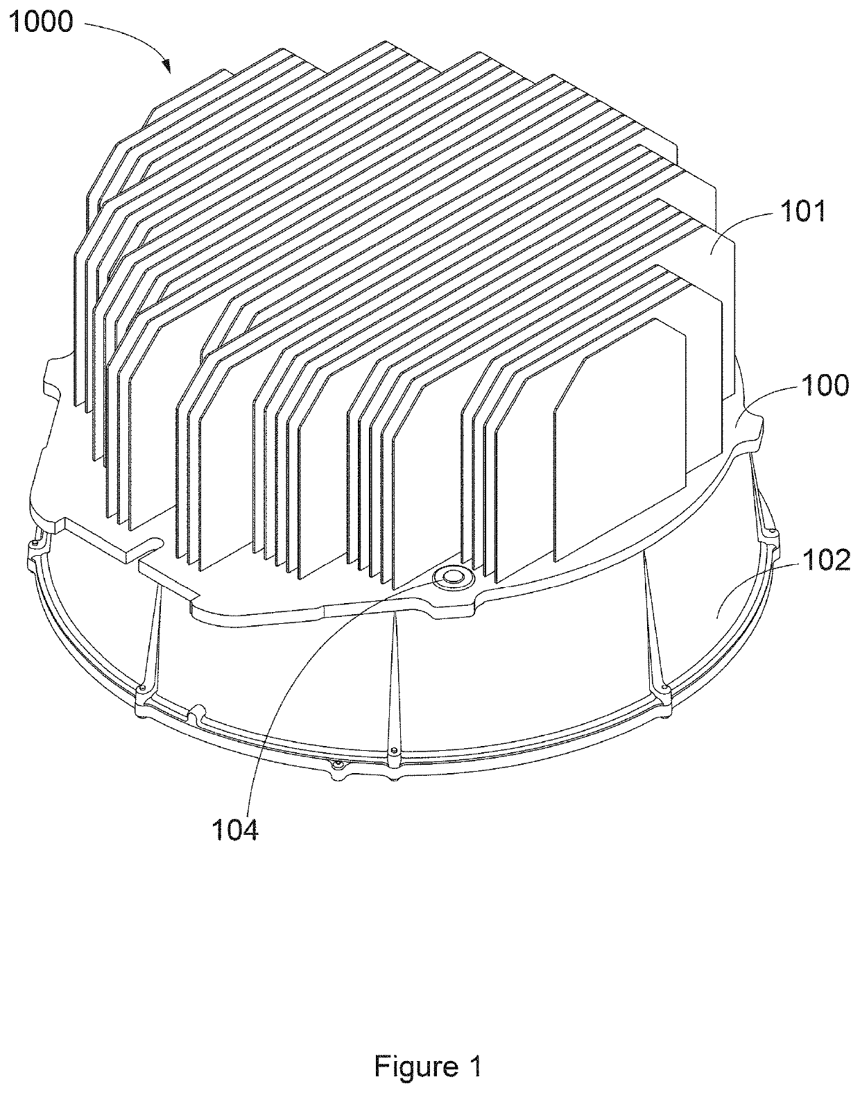
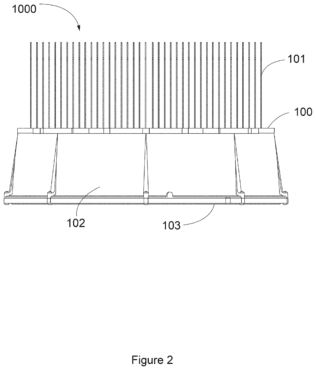
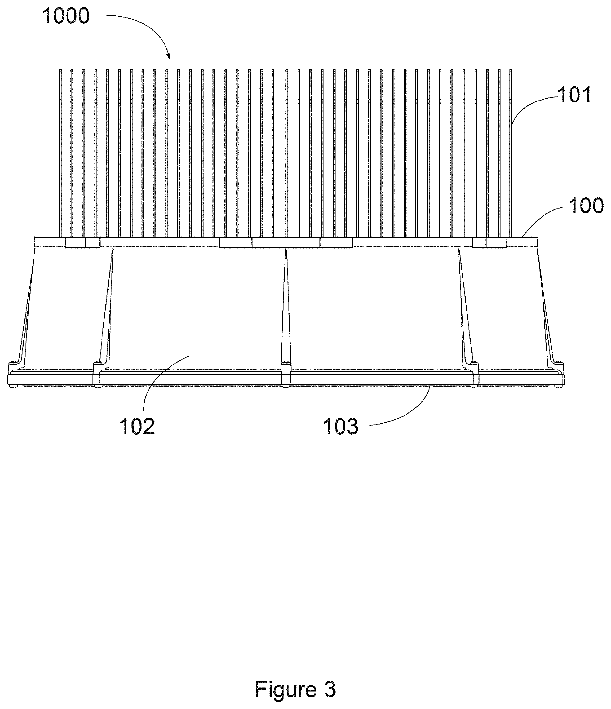
[0034]FIGS. 8 and 9 illustrate a first embodiment; note that for clarity no LEDs, LED boards, light directing and / or light redirecting devices, or electrical connections are illustrated (see FIGS. 17-18C for examples of at least some of the aforementioned). Here, a desiccant material 303 of assembly 300 is inserted into housing 102 of fixture 3000, and held in place via fastening devices 301 extending through a hold-down plate 302 and into a complementary portion 304 of housing 102. Here, desiccant material 303 is encased or contained in at least a gas permeable bag (it could be at least partially liquid permeable) so long as the material retains the desiccant. Such bag material can be the same or similar to that used in any of the wide variety of bagged desiccants that are put in packaging of products to absorb moisture. The material of the bag should allow sufficient transfer of moisture to the desiccant to be effective for the purposes described...

embodiment 2

E. Exemplary Apparatus Embodiment 2

[0036]FIGS. 10 and 11 illustrate a second embodiment; note that for clarity no LEDs, LED boards, light directing and / or light redirecting devices, or electrical connections are illustrated (see FIGS. 17-18C for examples of at least some of the aforementioned). Here, a desiccant material 400 is piped into, foamed, or otherwise formed in place in some portion of the lower hemisphere of the internal space of fixture 4000. In practice, any of a variety of moldable desiccants could be used; for example, those available from DryTech, Inc., Cookstown, N.J., USA.

[0037]Primary benefits of the present embodiment are such that (i) since desiccant 400 is physically near the site of condensation in the lower hemisphere of the internal space of the fixture, moisture is rapidly collected and removed from interior emitting face of glass 103, and (ii) the present approach can be readily implemented in a factory setting and therefore an amount / type / capacity of desic...

embodiment 3

F. Exemplary Apparatus Embodiment 3

[0038]FIGS. 12 and 13 illustrate a third embodiment; note that for clarity no LEDs, LED boards, light directing and / or light redirecting devices, electrical connections, or desiccant are illustrated (see FIGS. 17-18C for examples of at least some of the aforementioned). Here, a loose desiccant material (not shown) of assembly 500 is poured into a perforated aluminum alloy tube 501 within the internal space of fixture 5000. As can be seen, perforated tube 501 exists in sections, each section closed at opposite ends by a cap 503 once desiccant is inserted, the desiccant having a particle size larger than the perforations so to avoid spilling out (e.g., 2-4 mm diameter silica gel beads available from Dry & Dry, Brea, Calif., USA). One possible means of affixing tubes 501 in situ is to rely upon existing portions 304 of housing 102 by affixing a first portion of a bracket 502 to said portion 304 (e.g., via fastening device 301), and securing (e.g., via...


PUM

PropertyMeasurementUnit
volumeaaaaaaaaaa
water weightaaaaaaaaaa
temperatureaaaaaaaaaa

Abstract

Sealed LED lighting fixtures operated under certain conditions (e.g., outdoors, in cold ambient environments, at high operating current, and / or in non-hermetic environments) will oftentimes exhibit condensation on an inner surface of the emitting face of the fixture. When occurring, said condensation impairs the ability to produce useful light—namely, light harnessed and directed in a manner so to provide lighting for a task (or otherwise desired)—by diffusing light emitted from the lighting fixture. Envisioned are apparatus, methods, and systems to reduce moisture in sealed LED lighting fixtures so to reduce or eliminate condensation, and in a manner that addresses both fixtures already in the field and those being assembled.

Description

CROSS-REFERENCE TO RELATED APPLICATIONS[0001]This application claims priority under 35 U.S.C. § 119 to provisional U.S. application Ser. No. 62 / 791,941, filed Jan. 14, 2019, and provisional U.S. application Ser. No. 62 / 799,281, filed Jan. 31, 2019, both of which are hereby incorporated by reference in their entireties.I. TECHNICAL FIELD OF INVENTION[0002]The present invention generally relates to removing moisture from lighting fixtures. More specifically, the present invention relates to (i) in situ or field repairs of lighting fixtures which exhibit internal condensation under at least some conditions, and to (ii) apparatus, methods, and systems implemented in a factory setting so to avoid or minimize adverse impact from moisture in lighting fixtures.II. BACKGROUND OF THE INVENTION[0003]It is well known that lighting fixtures are designed to not only produce light, but produce useful light; namely, light harnessed and directed in a manner so to provide lighting for a task (or othe...

Claims


Application Information

Patent Timeline
Patent Type & Authority Patents(United States)
IPC IPC(8): B01D53/26F21V15/01
CPCB01D53/261F21V15/01B01D2253/106B01D2253/11B01D2253/112B01D2253/116F21V31/00F21Y2115/10F21V31/03
Inventor GROMOTKA, GABRIEL P.HERR, JR., KURT C.MCKEE, LUKE C.
Owner MUSCO
Learn More