Suspension system

a suspension system and suspension technology, applied in the direction of resilient suspensions, axle suspensions, cycle equipments, etc., can solve the problems of wheel and tire packaging problems, likely to not provide sufficient strength, etc., and achieve the effect of reducing and preferably eliminating feedback received

Active Publication Date: 2021-12-07
XTRAVEL SUSPENSION LLC
View PDF92 Cites 9 Cited by
  • Summary
  • Abstract
  • Description
  • Claims
  • Application Information

AI Technical Summary

Benefits of technology

[0018]It is contemplated that the suspension linkage arm can be configured such that the suspension linkage arm can vary in length as the vehicle moves causing movement of one or more of the linkage arms.
[0019]The shock assembly is therefore able to move with the linkage arms in order to not interrupt the positive and negative pressure within the multi-link suspension system. The suspension linkage arm is able to put the shock assembly at the optimal angle as the vehicle's suspension system is engaged. The suspension linkage arm is able to distribute the force absorbed through the shock assembly through the two linkage arms for strength, while not interrupting the multi-link suspension system.
[0020]By utilizing the above-described suspension system, the individualized movement of each of the linkage arms advantageously works to reduce and preferably eliminate any feedback received by the steering column such as when a wheel mounted to the wheel mount encounters an obstacle such as a rock. In prior art suspension systems, the driver of the vehicle would likely feel when the vehicle hits the obstacle due to sudden rotation of the steering wheel or handlebar. However, the above-described suspension system allows for such feedback to be substantially reduced and possibly eliminated such that the steering wheel or handlebar does not rotate or rotates insignificantly when an obstacle is struck by the wheel.

Problems solved by technology

However, such systems typically have wheel and tire packaging issues when trying to reach the correct tire axis geometry.
While the “V-type” suspension geometry provides the correct tire axis point by moving the single outer pivot into two separate pivots that geometrically converge on to one axis point, vehicles with such systems typically do not share the load of the shock or spring with more than one link point.
However, such configurations likely will not provide sufficient strength for the shock and will fail over time.

Method used


Image

  • Suspension system
  • Suspension system
  • Suspension system

Examples


Embodiment Construction

[0028]The following discussion provides many example embodiments of the inventive subject matter. Although each embodiment represents a single combination of inventive elements, the inventive subject matter is considered to include all possible combinations of the disclosed elements. Thus if one embodiment comprises elements A, B, and C, and a second embodiment comprises elements B and D, then the inventive subject matter is also considered to include other remaining combinations of A, B, C, or D, even if not explicitly disclosed.

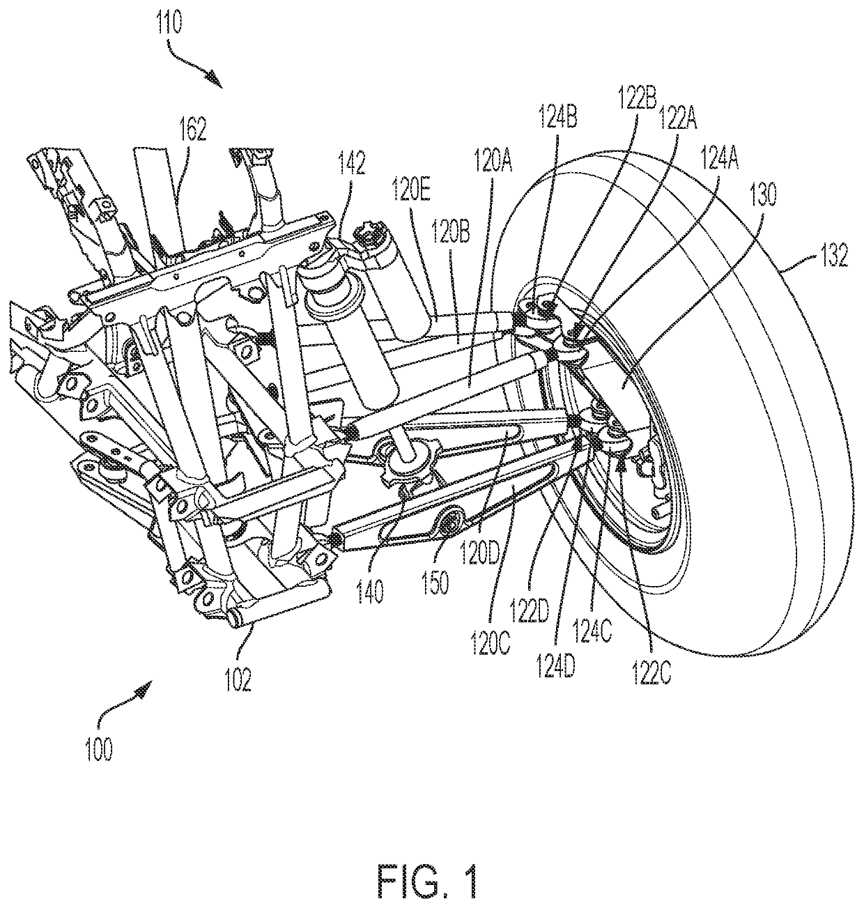
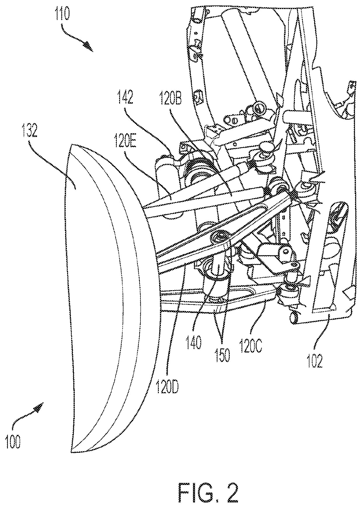
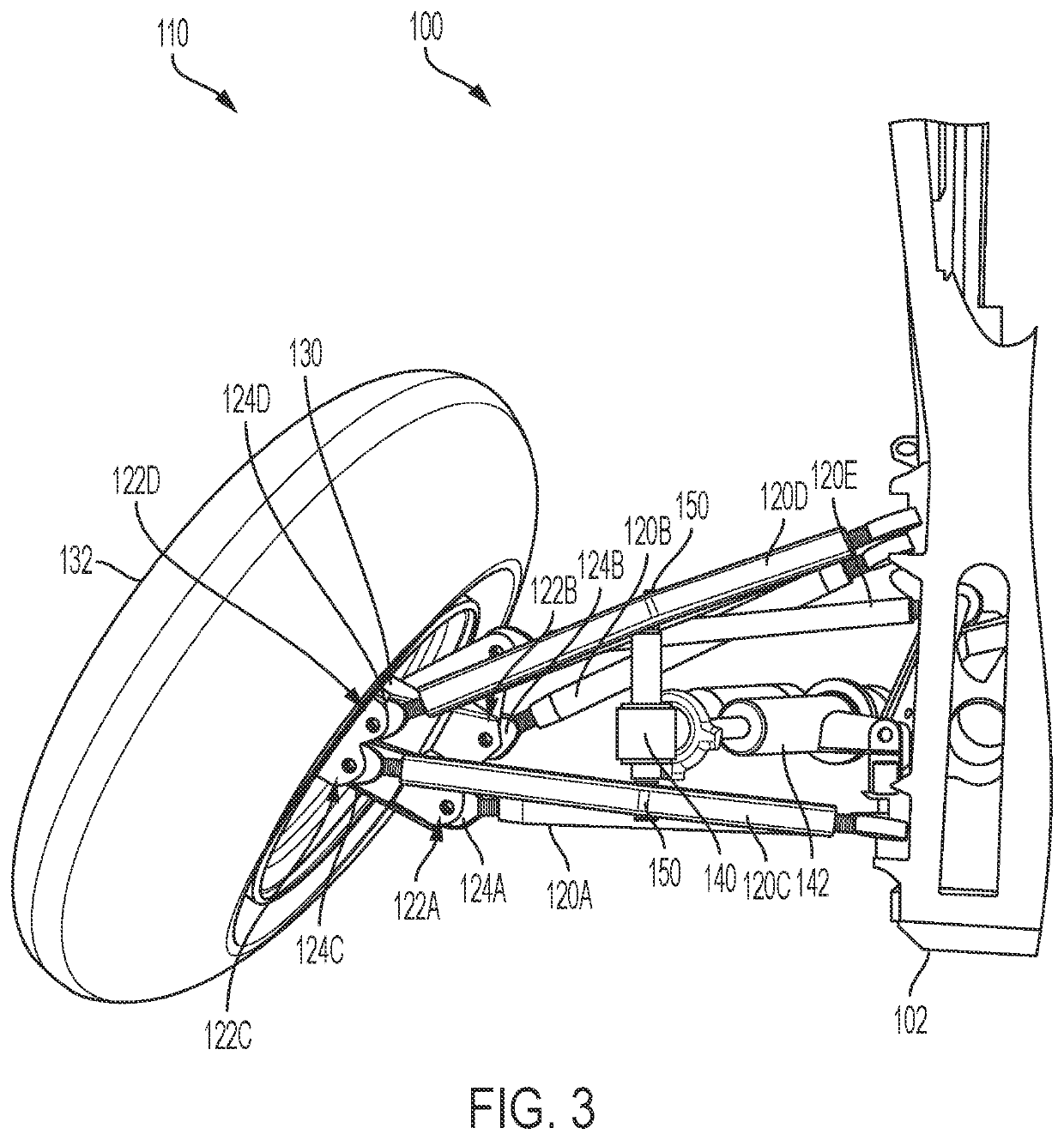
[0029]FIGS. 1-4 illustrates a suspension system 110 for a vehicle 100. Although vehicle 100 depicts an all-terrain vehicle, it is contemplated that the vehicle could comprise an automobile, truck, snowmobile or any other vehicle that requires an accurate level of control and function.

[0030]The suspension system 110 comprises a first linkage arm 120A that couples to a first point 122A on an upper portion of a wheel mount 130 at a first end and a chassis 102 ...


PUM


Abstract

Multi-link suspension systems for vehicle are described having various linkage arms that connect to distinct points of a wheel mount. Each of the linkage arms are preferably coupled to the wheel mount via a spherical ball joint and mounted such that they can independently move with respect to the other linkage arms. A shock assembly is preferably mounted between two of the linkage arms on a separate links that is configured to vary its length based on movement of one or both of the two linkage arms.

Description

[0001]This application claims priority to U.S. provisional patent application having Ser. No. 63 / 198,361 filed on Oct. 13, 2020. This and all other referenced extrinsic materials are incorporated herein by reference in their entirety. Where a definition or use of a term in a reference that is incorporated by reference is inconsistent or contrary to the definition of that term provided herein, the definition of that term provided herein is deemed to be controlling.FIELD OF THE INVENTION[0002]The field of the invention is suspension systems for vehicles.BACKGROUND[0003]The following description includes information that may be useful in understanding the present invention. It is not an admission that any of the information provided herein is prior art or relevant to the presently claimed invention, or that any publication specifically or implicitly referenced is prior art.[0004]Typical suspension designs for vehicles are designed around creating an offset axis point on the center of t...

Claims


Application Information

Patent Timeline
Patent Type & Authority Patents(United States)
IPC IPC(8): B60G3/20B62K25/24
CPCB60G3/20B62K25/24B60G2200/44B60G2204/143B60G2204/416B60G2204/422B60G2200/156B60G2204/129B60G13/005B60G2300/122B60G2200/184B60G7/003B62K5/08B62K2005/001B60G2200/144B60G2300/124B60G2300/07
Inventor BERARDI, NESTOR ALEXANDER
Owner XTRAVEL SUSPENSION LLC
Why Eureka
Try Eureka