No-hub pipe coupling method and apparatus

a technology of no-hub pipe and pipe coupling, which is applied in the direction of pipe-joints, sleeves/socket joints, mechanical devices, etc., can solve the problems of low strength connection, logistical problems, and difficulty in installation of handling and connecting separate parts, so as to improve the frictional connection, improve the axial connection, and increase the axial strength and stiffness

Active Publication Date: 2021-12-07
RELIANCE WORLDWIDE CORP
View PDF13 Cites 2 Cited by
  • Summary
  • Abstract
  • Description
  • Claims
  • Application Information

AI Technical Summary

Benefits of technology

[0008]The connector also includes at least two and preferably three or more separate axial straps each extending parallel to the longitudinal axis and equally spaced around that axis. Each of the first and second end clamps and the first and second intermediate clamps are fastened to each of the axial straps. The shield is also fastened to each of the axial straps. The first and second intermediate clamps are spaced an axial distance apart that is sufficiently large so that the pipe juncture may be located between the first and second intermediate clamps during use and so the first and second intermediate clamps may be tightened against the first and second pipe sections, respectively, during use. The shield and gasket have an axial length sufficient to extend to an axially outer side of the clamp straps of the first and second intermediate clamps. The axial connection provided by the axial straps is believed to provide improved resistance to axial separation of the pipe sections.
[0013]The no-hub connector is believed to provide more axial strength and stiffness than the prior art and to improve the axial connection between the band clamps. The no-hub connector is believed to improve the frictional connection between the band clamps and the pipe, and to improve the lateral strength and stiffness of the connection. The no-hub connector is believed to improve axial transmission of forces, to improve the radial clamping forces, to improve use of the radial clamping forces and to improve axial transmission of those forces.

Problems solved by technology

Clamping the rubber gasket to the radially outer surface of the pipes may create a low strength connection in the longitudinal direction as the gasket material is weak and may tear when the longitudinal force is great enough.
Ireland's use of two separate parts creates logistic problems and installation difficulties in handling and connecting separate parts.
Moreover, axial movement of the no-hub coupling relative to the added clamps may disrupt the function of the no-hub coupling.

Method used


Image

  • No-hub pipe coupling method and apparatus
  • No-hub pipe coupling method and apparatus
  • No-hub pipe coupling method and apparatus

Examples


first embodiment

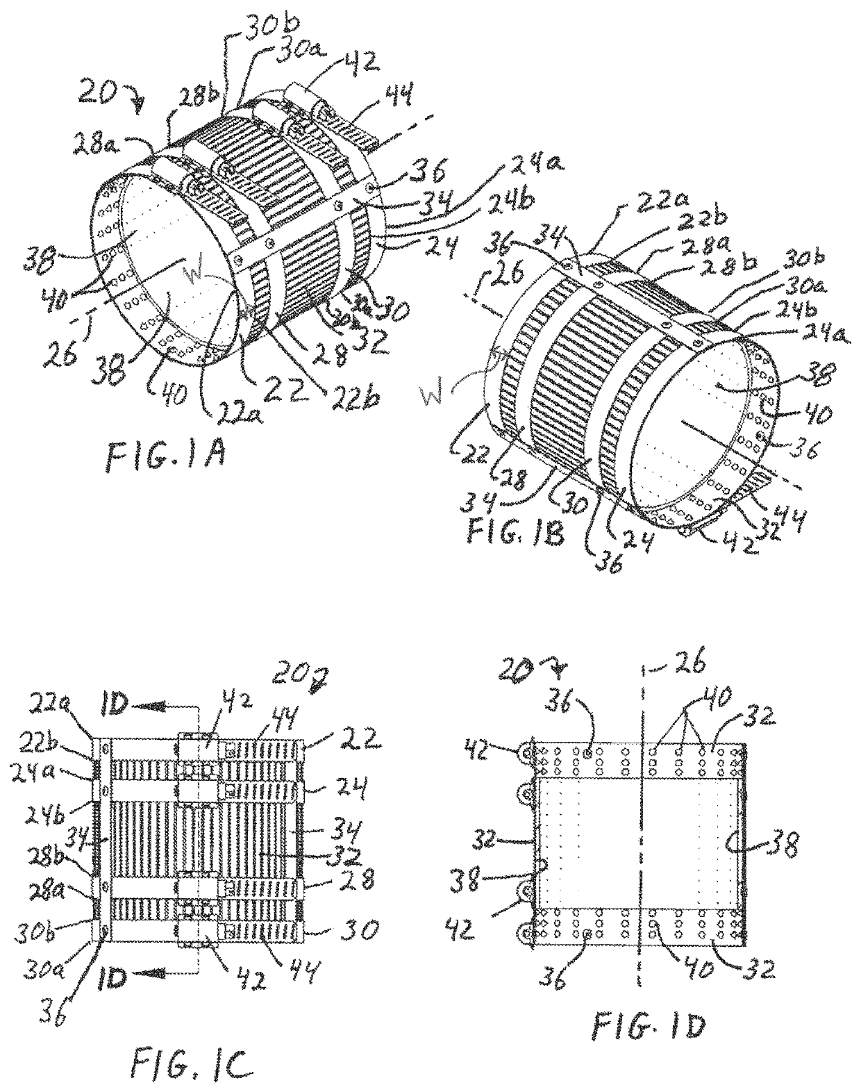
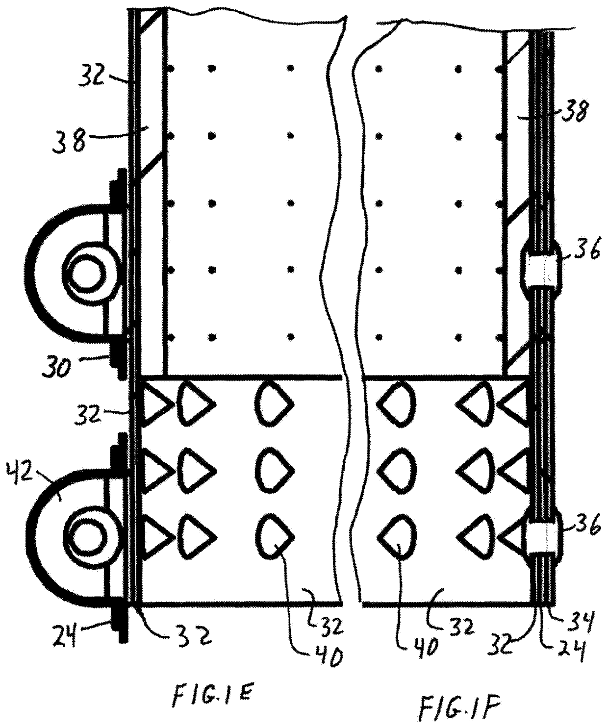
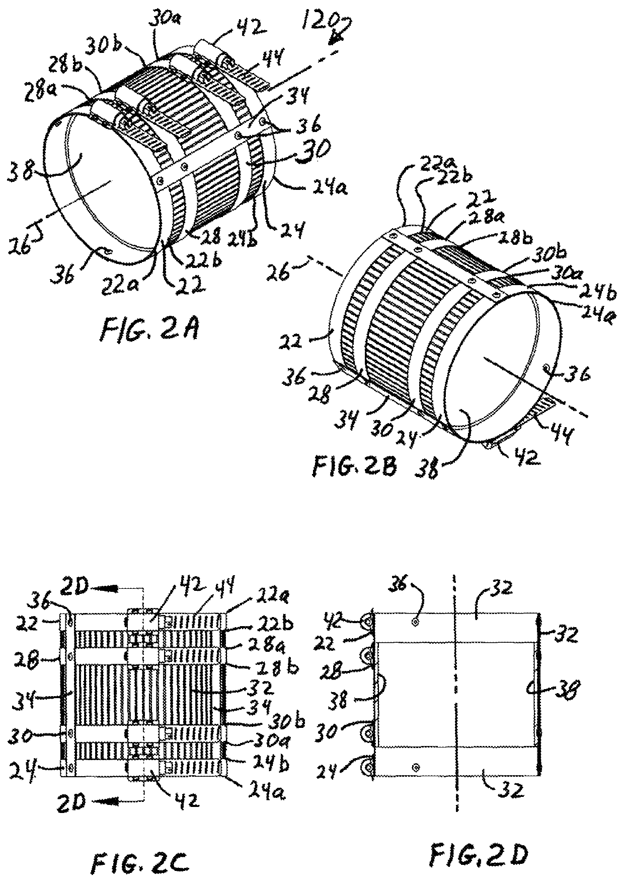
[0072]In use, the coupling assembly does not grip the pipe segments 21a, 21b the same way as the first embodiment because the gripping projections 40 are missing from the shield 132. Thus, the resistance to axial separation of the pipe sections 21a, 21b is believed to be less than for the embodiment of FIGS. 1A-1F for a given radial compression of the end bands 22, 24 and intermediate bands. But the other described advantages of connecting the gasket 38, shield 32 and clamps 22, 24, 28, 30 (and others when present) to axial straps 34 and to the shield 32 apply.

[0073]Moreover, the connector assembly 120 allows easy manipulation and installation of the gasket seal and an addition gripping mechanism engaging the pipe sections. A liquid seal and / or a fluid seal is established by clamping the gasket 34 to each of the pipe sections 21a, 21b using intermediate clamps 28, 30. The connector assembly 120 has the end clamps 22, 24 in position to further clamp the assembly 120 to the pipe secti...

third embodiment

[0076]Another difference is that no shield is interposed between the end clamps and the pipe sections 21a, 21b. In this third embodiment the shield 232 extends about the same axial distance as the gasket 238 and both have an axial end located between first and second end clamps 222, 224 and the first and second intermediate clamp 28, 30, closest to the respective end clamps. Thus, a first axially outer end of the shield 232 and gasket 238 ends between the first clamp 222 and adjacent intermediate clamp 28 and a second axially outer end of the shield 232 and gasket 238 ends between the second clamp 224 and its adjacent intermediate clamp 30. A gap or space exists between the end clamps 222, 224 and the intermediate clamp 28, 30 nearest each end clamp, and that gap or space is preferably the width of the circumferential clamp strap of the end clamps, which are preferably all the same width. But the axial gap or space may vary.

[0077]The shield 232 is advantageously adhered to the gaske...


PUM


Abstract

A no-hub connector has a tubular gasket enclosed by a tubular shield and includes two end clamps and two intermediate clamps to tighten the connector around the ends of two pipe sections joined by the connector. Axially extending straps are fastened to each ring clamp, and fastened to the shield at the location of each ring clamp encircling the shield. An inward facing shield surface has optional gripping projections and the shield may optionally extend axially past the intermediate clamps to the end clamps. The inward facing surface of the end clamps may have optional gripping projections if the shield does not extend axially to the end clamps.

Description

CROSS-REFERENCE TO RELATED APPLICATIONS[0001]The application claims the benefit under 35 U.S.C. § 119(e) to Provisional Patent Application No. 62 / 731,624 filed Sep. 14, 2018, the entire contents of which are incorporated herein by reference.STATEMENT RE: FEDERALLY SPONSORED RESEARCH / DEVELOPMENT[0002]Not ApplicableBACKGROUND[0003]No-hub couplings are used to join the ends of two metal pipes where the ends do not have spigots or ends configured to mate and engage with each other, such as mating threaded ends or mating male and female ends. The no-hub couplings are used primarily with metal pipes because plastic pipes are adhesive welded together using intermediate connectors and because the plastic pipes have a much lower ability to withstand the radial clamping forces used to create fluid tight seals on the no-hub connectors.[0004]U.S. Pat. No. 5,431,458 to Schaub discloses a no-hub coupling using a tubular gasket with a corrugated metal shield outside the gasket and four separate, c...

Claims


Application Information

Patent Timeline
Patent Type & Authority Patents(United States)
IPC IPC(8): F16L21/06
CPCF16L21/06F16L21/005
Inventor O'NEIL, VIRGIL
Owner RELIANCE WORLDWIDE CORP
Why Eureka
Try Eureka