Device for use in hysteroscopy

a technology for hysteroscopy and portable devices, which is applied in the field of portable devices for hysteroscopy, can solve the problems of large amount of permanently or semi-permanently installed technical equipment, complex equipment, and difficulty in purchasing and maintaining equipment, and achieves the effect of requiring skills and training for sta

Active Publication Date: 2022-01-04
LINA MEDICAL INT OPERATIONS AG
View PDF46 Cites 0 Cited by
  • Summary
  • Abstract
  • Description
  • Claims
  • Application Information

AI Technical Summary

Benefits of technology

[0010]It is an object of the invention to provide an improved device for hysteroscopy particularly relative to manoeuvrability and the ability to navigate inside the uterus.

Problems solved by technology

In the medical field, the large amount of permanently or semi-permanently installed technical equipment is challenging.
The costs for purchasing and costs for maintaining the equipment, and the complexity necessitate skills and training for the staff.
Additionally, the technical equipment takes up space, they require fixed power supply and / or supply of fluids etc., and they may be impossible to move close to the practitioner during the surgery and therefore they may sometimes be in the way for the staff and be difficult to use.
Sterility can be accomplished by using a device only once, but typically, the large electrical fixtures including endoscopes and monitors of an operating room are too expensive to be used only once.
The existing endoscopes are complicated to use and require adaption of settings between the scope and the control unit.
Additionally, manoeuvrability of the scope inside narrow body cavities such as the uterus is complicated and the mechanical structure required for manoeuvring the scope is typically expensive an not suitable for single use devices.

Method used


Image

  • Device for use in hysteroscopy
  • Device for use in hysteroscopy
  • Device for use in hysteroscopy

Examples


Embodiment Construction

[0074]It should be understood that the detailed description and specific examples, while indicating embodiments of the invention, are given by way of illustration only, since various changes and modifications within the spirit and scope of the invention will become apparent to those skilled in the art from this detailed description.

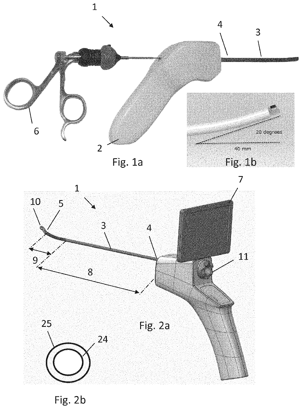
[0075]Referring to FIGS. 1a, 1b, 2a, and 2b, the tissue visualization device 1 comprises an image capturing structure configured to capture pictures of tissue.

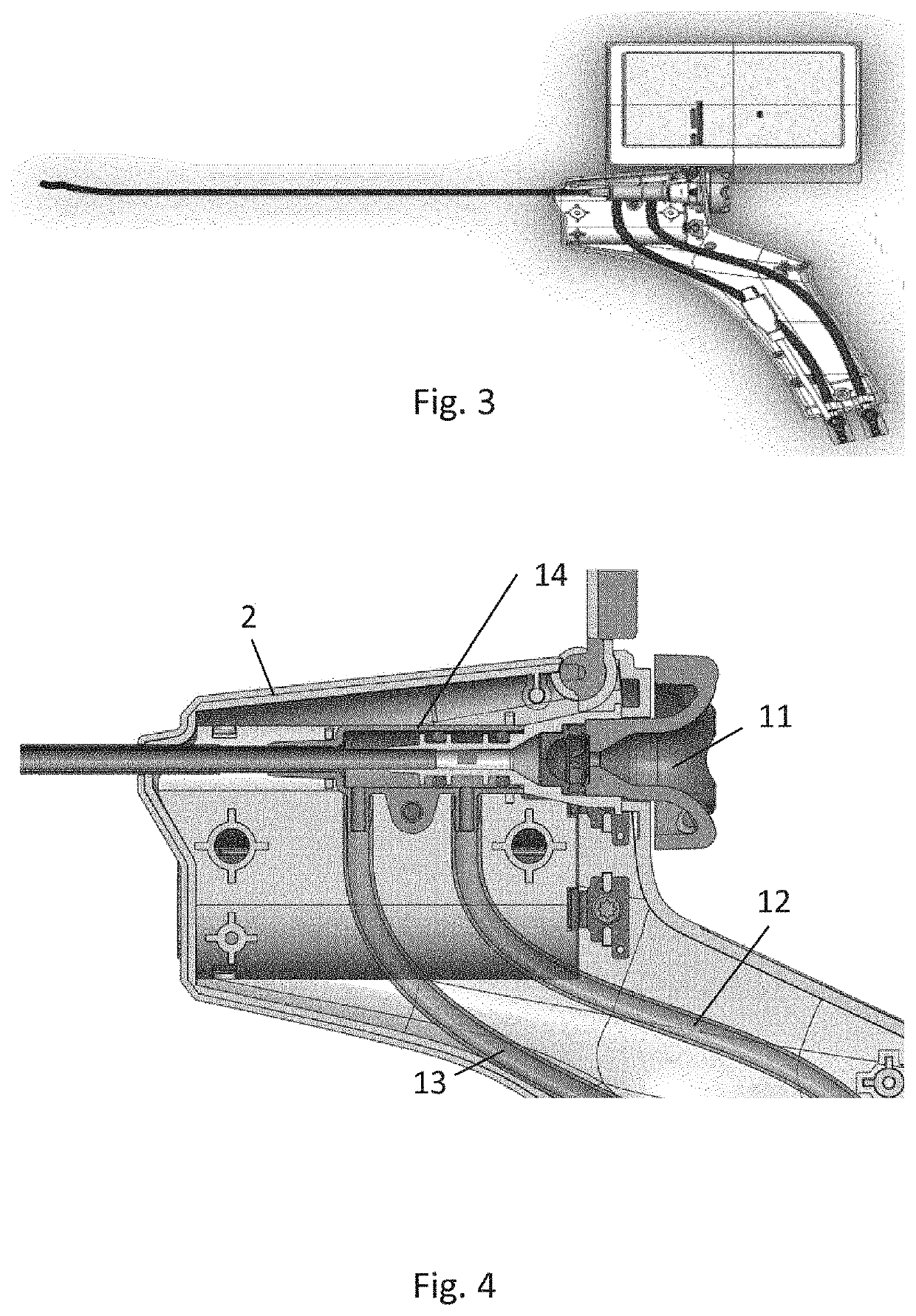
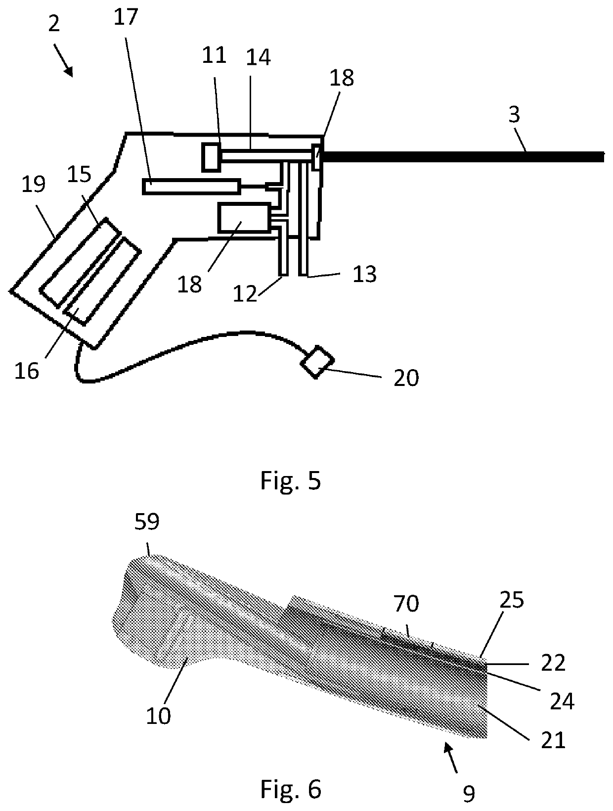
[0076]The device 1 comprises a hand held control unit 2 and an elongated member 3 connected to the control unit 2. The elongated member extends from a proximal end 4 to a distal end 5. The distal end is shown in FIG. 1b illustrating that the curved portion forms an angle of 20 degrees to the straight axis. The curved distal end is also only shown in FIG. 2a.

[0077]FIG. 1s illustrates a surgical tool 6 which is inserted in a tool conduit of the elongated member.

[0078]FIG. 2a illustrates a monitor 7 w...


PUM


Abstract

A device for visualization of internal tissue of a patient's uterus having a hand-held control unit, an elongated member, and an image capturing tip. To increase the manoeuvrability of the image capturing tip, the elongated member forms a straight portion extending along a straight axis and a curved portion forming a curvature away from the straight axis, the curved portion being between the image capturing tip and the straight portion. By rotation of an inner tube in an outer tube, the image capturing structure will move along a circular path without being rotated about the centre axis of the elongated member.

Description

BACKGROUND OF THE INVENTIONField of the Invention[0001]The present invention relates to a portable device for use in hysteroscopy.Brief Description of the Related Art[0002]Gynaecologists use hysteroscopy in standard examination procedures, both office-based procedures and in hospital procedures where an endoscope is inserted into the uterus e.g. for inspecting the lining.[0003]For the practitioner, the field of diagnostic imaging, for example hysteroscopy, has allowed for the viewing of objects, internal mechanisms and the like with minimal disruption.[0004]Such imaging tools have been used in a wide variety of settings for detailed inspection, including but not limited to the use and application in the field of medicine.[0005]In the medical field, the large amount of permanently or semi-permanently installed technical equipment is challenging. The costs for purchasing and costs for maintaining the equipment, and the complexity necessitate skills and training for the staff.[0006]Add...

Claims


Application Information

Patent Timeline
Patent Type & Authority Patents(United States)
IPC IPC(8): A61B1/303A61B1/00A61B1/005A61B1/015A61B1/018A61B1/045A61B1/05A61B1/06A61B17/42A61B90/00A61B17/29A61B17/00A61M25/00A61B90/30
CPCA61B1/303A61B1/00052A61B1/0052A61B1/0055A61B1/0057A61B1/00078A61B1/015A61B1/018A61B1/045A61B1/051A61B1/0684A61B17/42A61B17/4241A61B90/37A61B1/05A61B17/29A61B2017/00017A61B2017/00115A61B2017/00221A61B2017/00309A61B2017/00331A61B2017/00734A61B2017/00738A61B2017/4216A61B2090/064A61B2090/309A61B2217/005A61B2217/007A61M25/0054
Inventor JENSEN, JACOB KOLLERUP
Owner LINA MEDICAL INT OPERATIONS AG
Why Eureka
Try Eureka