Shower head and processing device
a technology of processing device and shower head, which is applied in the direction of coating, chemical vapor deposition coating, metallic material coating process, etc., can solve the problems of difficult inability to carry out excellent uniform processing to the surface to be processed of the processing object, and interference with the exhaustion of gas injected to the central part of the processing object. , to achieve the effect of reducing the pressure difference between the shower head and th
- Summary
- Abstract
- Description
- Claims
- Application Information
AI Technical Summary
Benefits of technology
Problems solved by technology
Method used
Image

Examples
second embodiment
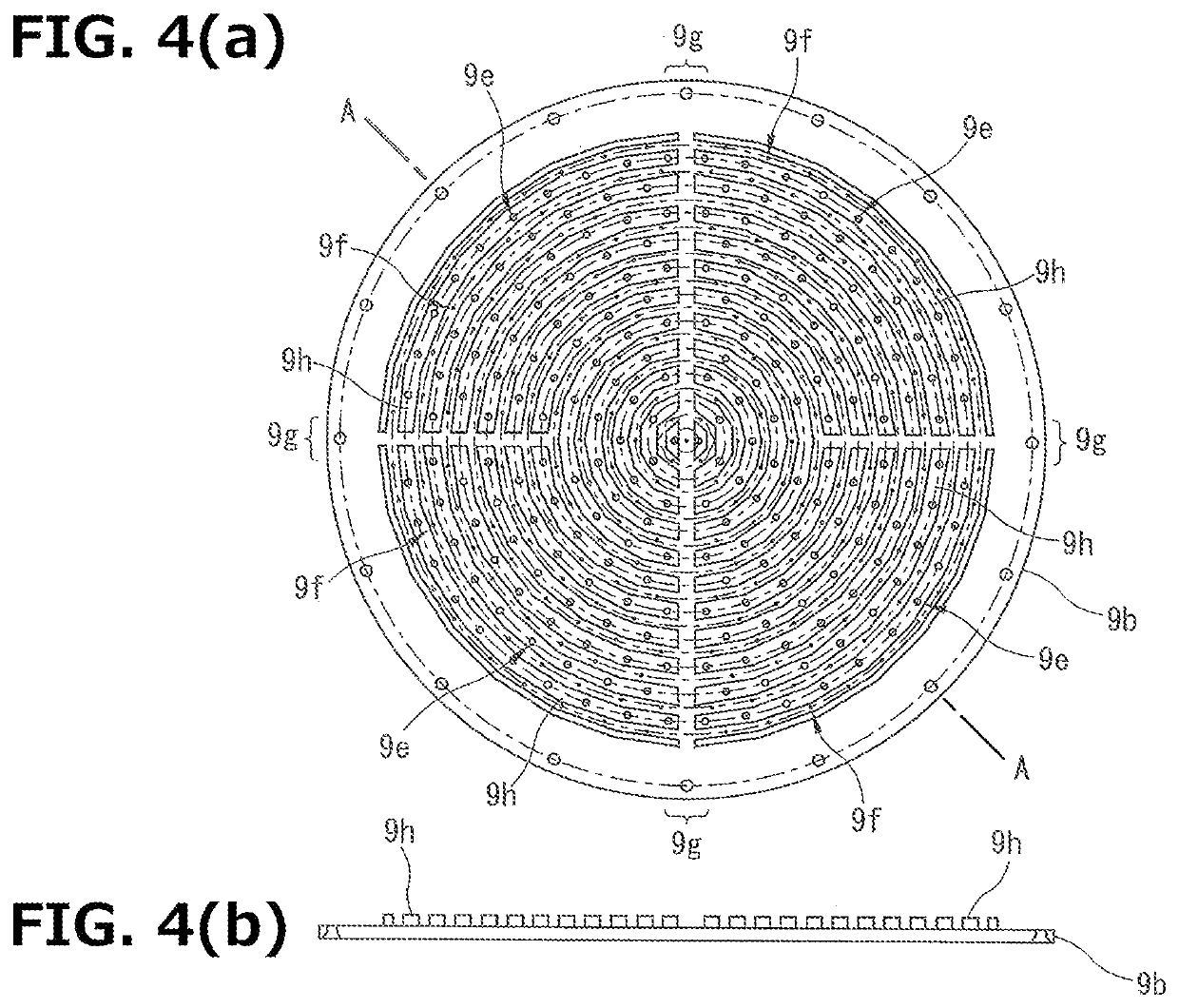
[0062]The ozone processing device 10 according to the present invention is provided with first and second gas injection holes 9e and 9f, from which different kinds of gasses are injected, on the side facing the wafer 3 of the shower head 9, such that two different kinds of gasses are supplied from the shower head 9 to the wafer 3.
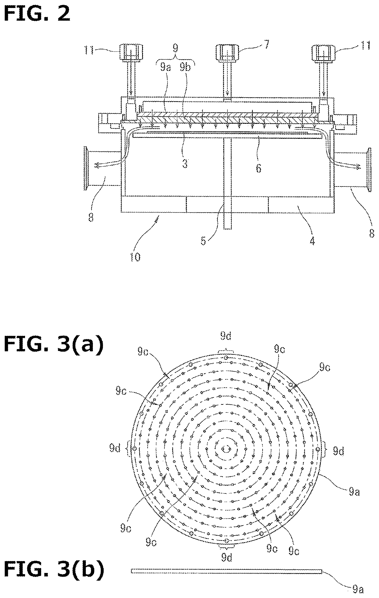
[0063]The ozone processing device 10 is provided with a processing chamber 4. A rotation stage 6 and the shower head 9 are provided inside the processing chamber 4. In addition, a gas supply port 7 for supplying ozone gas and gas supply ports 11 for supplying an added gas (such as a TEOS gas and an unsaturated hydrocarbon gas) are provided above the processing chamber 4.
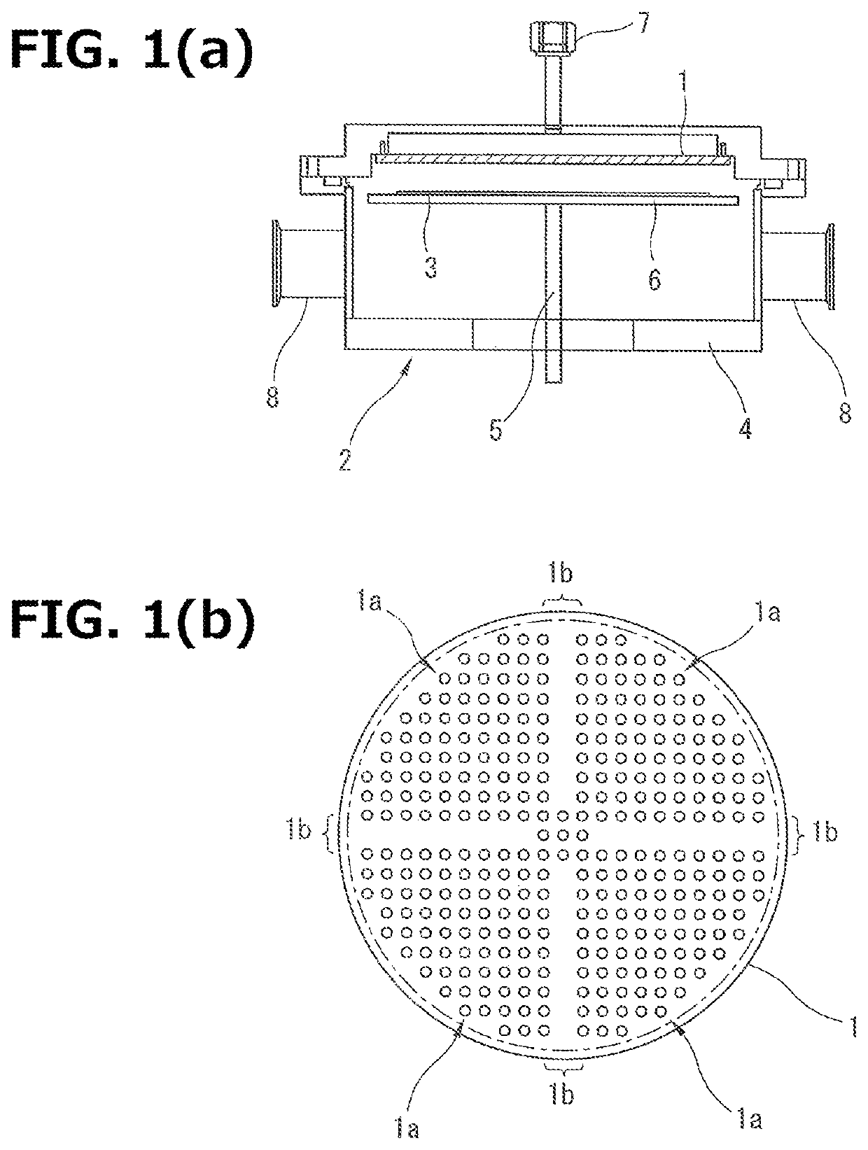
[0064]The shower head 9 is provided inside the processing chamber 4, and is provided at a position away from the wafer 3 placed on the rotation stage 6 so as to face the processing surface of the wafer 3. The shower head 9 is provided with a first shower head 9a and a second shower head 9b. ...
first embodiment
[0065]As shown in FIG. 3, similar to the shower head 1 explained in the first embodiment, the first shower head 9a is provided with, on a surface facing the wafer 3, gas injection holes 9c from which ozone gas as a material gas is injected and exhaust gas flow path portions 9d extending from the outer peripheral part to the central part of the first shower head 9a.
[0066]For example, the gas injection holes 9c are arranged on a plurality of concentric circles (except the exhaust gas flow path portions 9d) having different diameters at equal intervals, centering on the surface of the first shower head 9a which faces the wafer 3. In addition, the arrangement form of the gas injection holes 9c is not limited to the embodiment, and it can be arbitrary set.
[0067]The exhaust gas flow path portions 9d are areas in which gas is not injected. The exhaust gas flow path portions 9d are areas in which the gas injection holes 9c are not formed, and, for example, a plurality of the exhaust gas fl...
fifth embodiment
[0097]FIG. 12 (a) is a characteristic diagram showing the relationship between a gas supply flow rate and each of the pressure (Pc) in the center of the wafer 3, the pressure (Pa) at the periphery of the wafer 3 and the pressure (Pe) in the exhaust port 8 of the ozone processing device 18 according to the
[0098]FIG. 13 (a) is a characteristic diagram showing the relationship between a gas supply rate and each of the pressure (Pc) in the center of the wafer 3, the pressure (Pa) at the periphery of the wafer 3 and the pressure (Pe) in the exhaust port 8 of the ozone processing device 27 according to the comparative embodiment. As shown in FIG. 13 (b), the ozone processing device 27 according to the comparative embodiment is one provided with a shower head 28 according to the comparative embodiment. As shown in FIG. 13 (c), gas injection holes 28a are uniformly formed on the surface of the shower head 28 which faces the wafer 3.
[0099]As is clear from the comparison between the character...
PUM
| Property | Measurement | Unit |
|---|---|---|
| pressure | aaaaa | aaaaa |
| areas | aaaaa | aaaaa |
| circular shape | aaaaa | aaaaa |
Abstract
Description
Claims
Application Information
 - R&D
- Intellectual Property
- Life Sciences
- Materials
- Tech Scout
- Unparalleled Data Quality
- Higher Quality Content
- 60% Fewer Hallucinations
Browse by: Latest US Patents, China's latest patents, Technical Efficacy Thesaurus, Application Domain, Technology Topic, Popular Technical Reports.
© 2025 PatSnap. All rights reserved.Legal|Privacy policy|Modern Slavery Act Transparency Statement|Sitemap|About US| Contact US: help@patsnap.com