Shockproof element and electronic device

a technology of electronic devices and elements, applied in the direction of electric apparatus casings/cabinets/drawers, instruments, liquid fuel engines, etc., can solve the problems of reducing the production speed of electronic devices, unable to decrease the vibration generated by electronic elements, and user discomfort, so as to reduce the vibration, reduce the vibration, and avoid the effect of user discomfor

Active Publication Date: 2022-01-25
PEGATRON
View PDF45 Cites 0 Cited by
  • Summary
  • Abstract
  • Description
  • Claims
  • Application Information

AI Technical Summary

Benefits of technology

[0006]In view of the foregoing, an objective of this disclosure is to provide a shockproof element and an electronic device configured with the shockproof element. Compared with the conventional art, the shockproof element of this disclosure can decrease the vibration generated by the electronic element so as to avoid the uncomfortable of the user. In addition, the shockproof element of this disclosure can fix the electronic element inside the electronic device, so it can substitute for the conventional screws, thereby reducing the manufacturing cost and improving the production speed.
[0018]As mentioned above, the shockproof element of this disclosure can decrease the vibration generated by the electronic element, thereby avoiding the uncomfortable of the user. In addition, the shockproof element of this disclosure includes a hollow column, which can pass through the through hole of the fastening portion of the electronic element for fixing the electronic element. Moreover, the housing of the electronic device has a positioning pillar, which can pass through the hollow column for fixing the electronic element inside the electronic device. Accordingly, the shockproof element of this disclosure can not only decrease the vibration generated by the electronic element, but also provide the fixing function of the conventional screws, thereby reducing the manufacturing cost of the electronic device and improving the production speed.

Problems solved by technology

However, the electronic components may generate vibration during operation, which causes the uncomfortable of the user.
However, the above-mentioned conventional fixing method can merely provide the fixing function, but cannot decrease the vibration generated by the electronic element (no shockproof function).
Moreover, the above-mentioned conventional fixing method needs an additional tool (e.g. a screwdriver), which may decrease the production speed of the electronic device and increase the manufacturing cost.

Method used


Image

  • Shockproof element and electronic device
  • Shockproof element and electronic device
  • Shockproof element and electronic device

Examples


Embodiment Construction

[0029]The present disclosure will be apparent from the following detailed description, which proceeds with reference to the accompanying drawings, wherein the same references relate to the same elements.

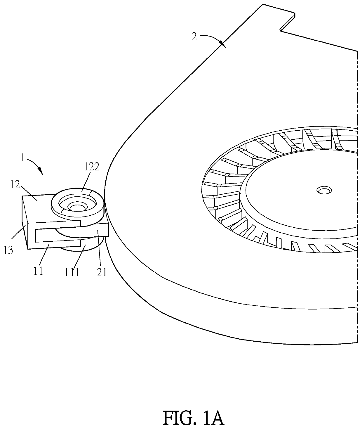
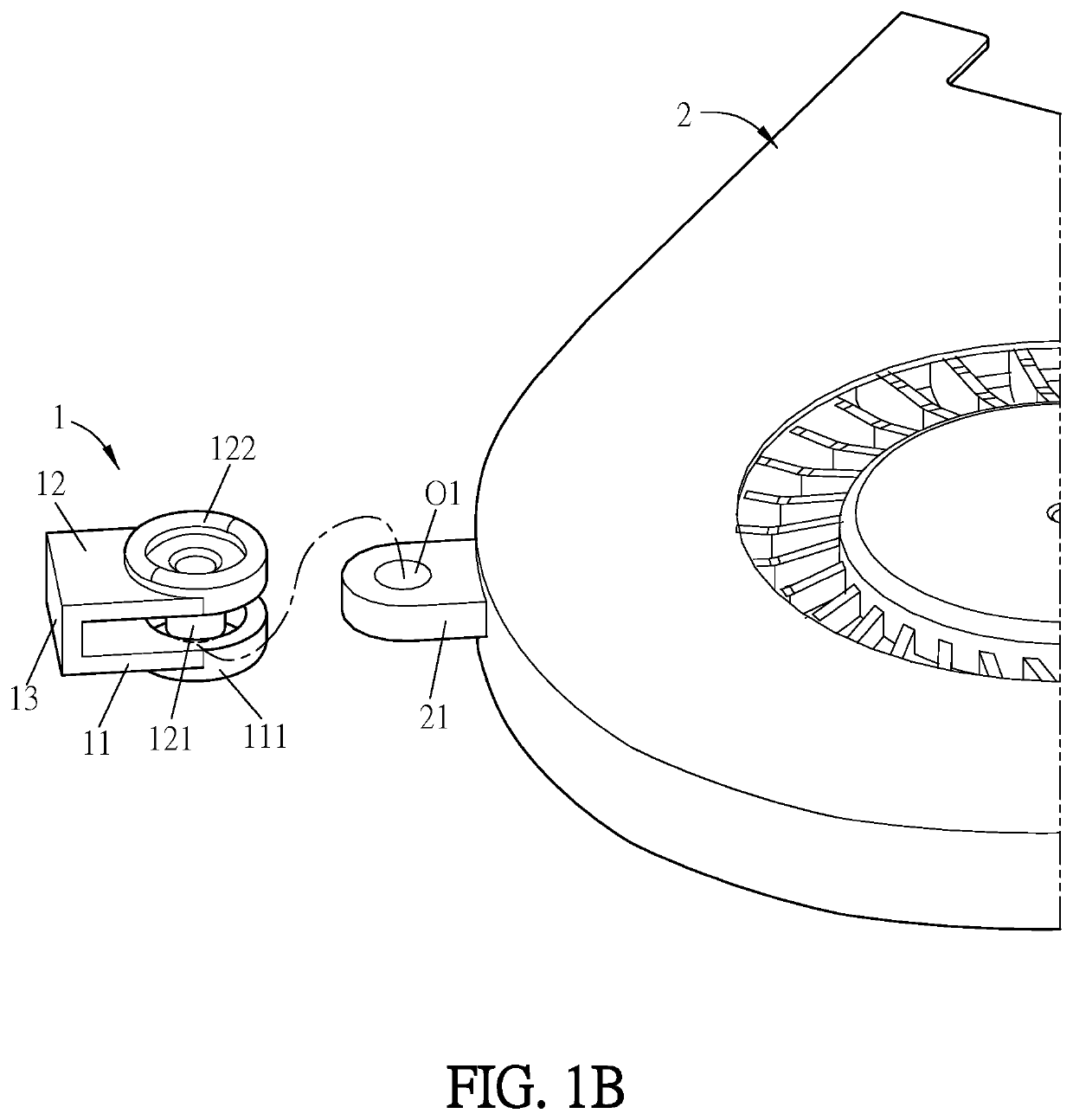
[0030]FIG. 1A is a schematic diagram showing a shockproof element of this disclosure in cooperated with an electronic element, and FIG. 1B is a schematic diagram showing the electronic element and the shockproof element of this disclosure, wherein the electronic element and the shockproof element are separated. Referring to FIGS. 1A and 1B, in this embodiment, the shockproof element 1 is applied to an electronic element 2. In this case, the electronic element 2 is a fan. To be noted, the electronic element 2 can be any of other electronic elements such as, for example but not limited to, a hard disk, a mainboard, a graphic card, or the likes, and this disclosure is not limited thereto.

[0031]The cooperation and configuration of the shockproof element 1 and the electronic element 2 wil...


PUM


Abstract

A shockproof element is applied to an electronic element. The shockproof element includes a first elastic portion, a second elastic portion and a connecting portion. The first elastic portion defines an opening. The second elastic portion is disposed corresponding to the first elastic portion. The second elastic portion includes a hollow column. The hollow column extends from the second elastic portion into the opening of the first elastic portion. The hollow column can fix the electronic element, and the first elastic portion and the second elastic portion jointly hold the electronic element. The connecting portion connects to the first elastic portion and the second elastic portion. An electronic device, which includes the shockproof element, the electronic element, a first housing and a second housing, is also provided.

Description

CROSS REFERENCE TO RELATED APPLICATIONS[0001]This Non-provisional application claims priority under 35 U.S.C. § 119(a) on Patent Application No(s). 108112342 filed in Taiwan, Republic of China on Apr. 9, 2019, the entire contents of which are hereby incorporated by reference.BACKGROUNDTechnology Field[0002]The present disclosure relates to a shockproof element and an electronic device, and, in particular, to a shockproof element capable of fixing an electronic element and an electronic device including the shockproof element and the electronic element.Related Art[0003]With the progress of science and technology, the functionality and convenience of electronic devices have been continuously improved, and the improved electronic devices have been widely used. For example, the electronic devices include tablets, cellular phones, global position systems (GPS), personal digital assistants, palm-size PCs, and information appliances. Such electronic products are provided with electronic co...

Claims


Application Information

Patent Timeline
Patent Type & Authority Patents(United States)
IPC IPC(8): G06F1/16F16F15/04
CPCG06F1/1658F16F15/04F16F1/187F04D29/668H05K5/0217F16F2230/0029F16F2230/0041F16F15/08F16F2230/0023
Inventor LIN, CHIAO-YICHEN, PO-CHUN
Owner PEGATRON
Why Eureka
Try Eureka