
Seismic retention assembly for weigh module and method

a technology of securing equipment and assembly, which is applied in the direction of weighing relieving/resting mechanisms, machine frames, stands/trestles, etc., can solve the problems of equipment being unrestrained, affecting the safety of equipment,

Active Publication Date: 2022-02-01
CONECRAFT
View PDF12 Cites 0 Cited by
  • Summary
  • Abstract
  • Description
  • Claims
  • Application Information

AI Technical Summary

Benefits of technology

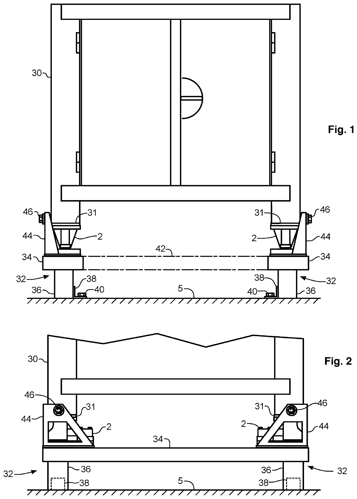
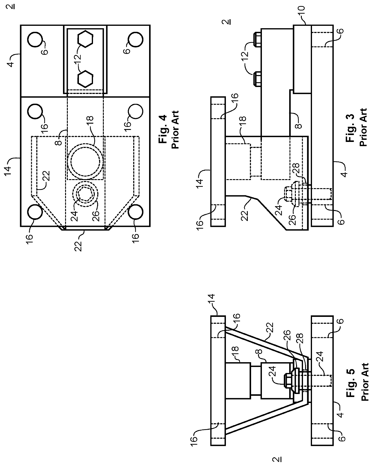
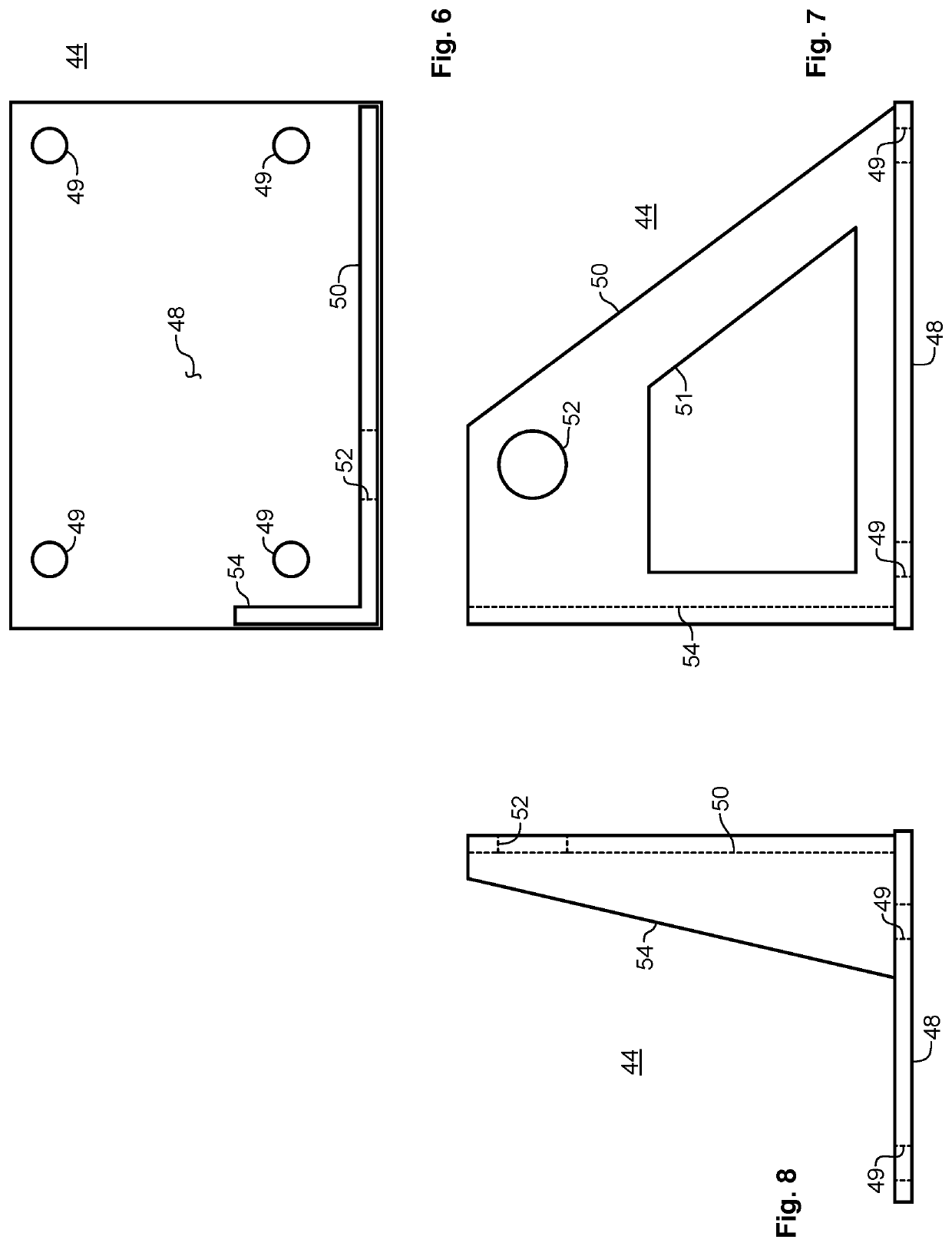
The present invention provides a seismic retention assembly for equipment that is supported above a support structure by one or more weigh modules. The assembly includes a seismic bracket with a mounting plate and a flange fixed to the mounting plate, which has a retention aperture formed through it. The assembly also includes a retention fastener with an attachment means for rigid connection to the equipment and a shank with a boss at a distal end thereof. The attachment means is placed in alignment with the retention aperture and the shank is fixedly engaged with the equipment, while providing clearance between the shank and the boss. This allows for unrestricted operation of the weigh module and prevents movement of the equipment beyond the clearance, regardless of seismic events. The invention also provides a method for installing the seismic retention assembly.

Problems solved by technology

However, over the lives of weigh modules, there may be dynamic events where forces acting on a weigh module exceed its maximum load rating.
Events of particular concern are seismic events, such as earthquakes, where very large forces may act upon such weigh modules, which may induce critical, and highly dangerous, failures.
When such a failure occurs, the underlying support of whatever type of equipment that rests upon the weigh modules, may be lost entirely, and such equipment may become unrestrained, allowing it to move freely under whatever forces may exist after the failure.
This results in a highly dangerous situation, particularly where the nature and content of the equipment is, in an of itself, dangerous.
For example, dangerous or flammable materials may be contained in such equipment.

Method used


Image

  • Seismic retention assembly for weigh module and method
  • Seismic retention assembly for weigh module and method
  • Seismic retention assembly for weigh module and method

Examples


Embodiment Construction

[0035]Illustrative embodiments and exemplary applications will now be described with reference to the accompanying drawings to disclose the advantageous teachings of the present invention.

[0036]While the present invention is described herein with reference to illustrative embodiments for particular applications, it should be understood that the invention is not limited thereto. Those having ordinary skill in the art and access to the teachings provided herein will recognize additional modifications, applications, and embodiments within the scope hereof, and additional fields in which the present invention would be of significant utility.

[0037]In considering the detailed embodiments of the present invention, it will be observed that the present invention resides primarily in combinations of steps to accomplish various methods or components to form various apparatus and systems. Accordingly, the apparatus and system components, and method steps, have been represented where appropriate...


PUM


Abstract

A seismic retention assembly for retaining equipment supported on weigh modules in place during and after a seismic event. The assembly includes a seismic bracket with a mounting plate and a flange that extends beyond the weigh module, and with a retention aperture formed through the flange, located adjacent to the equipment. A retention fastener includes a nut fixed to the equipment in alignment with the aperture, and also a bolt that passes through the aperture and engages the nut. Clearance between the bolt and the aperture enables unimpeded operation of the weigh module during normal use, but limits movement during a seismic event.

Description

BACKGROUND OF THE INVENTIONRelated Applications[0001]None.Field of the Invention[0002]The present invention relates to securing equipment supported upon weigh modules during seismic events. More particularly, the present invention relates to a seismic retention assembly and method for securing equipment in the event that a seismic event damages weigh modules that supports such equipment.Description of the Related Art[0003]Weigh modules, including strain gauge type weigh modules, are utilized in a wide range of industrial and commercial applications. Weigh modules measure static and dynamic forces acting upon them, and provide an electronic signal indicating the weight and / or dynamic forces acting upon them. For example, a liquid tank can be supported upon a plurality of weigh modules, whose output signals are combined to provide an accurate measure of the weight of the tank and its content. By subtracting the tare weight of the tank, the dynamic weight of the tank contents can be mo...

Claims


Application Information

Patent Timeline
Patent Type & Authority Patents(United States)
IPC IPC(8): F16M13/02F16M11/22F16M11/04
CPCF16M13/02F16M11/04F16M11/22F16M7/00G01G23/02
Inventor AUSTIN, JAMES A.GETRUM, JEFFREY O.
Owner CONECRAFT
Learn More