
Resistance spot welding method and resistance spot welding apparatus

a welding apparatus and resistance spot technology, applied in the direction of resistance electrode holders, electrode features, manufacturing tools, etc., can solve the problems of decreasing the density of heat generation in the welding area during the main welding, increasing the diameter of the leading end of the electrode, and failing to secure an appropriate size of the molten part (an appropriate diameter of the weld nugget) before the main welding end, etc., to achieve the effect of sufficient welding accuracy

Active Publication Date: 2022-02-15
TOYOTA JIDOSHA KK
View PDF13 Cites 0 Cited by
  • Summary
  • Abstract
  • Description
  • Claims
  • Application Information

AI Technical Summary

Benefits of technology

The present patent provides a resistance spot welding method and apparatus that can achieve a sufficient level of welding accuracy during preliminary current application and main welding. By correcting the welding condition based on information on the workpiece and the likelihood of welding abnormalities, such as expulsion, the method can secure an appropriate size of a molten part and achieve a sufficient level of welding accuracy regardless of the amount of wearing of the electrodes. Additionally, the method allows for continued current application after the welding condition is corrected to prevent welding abnormalities. The resistance spot welding apparatus can also secure an appropriate size of a molten part and achieve a sufficient level of welding accuracy by correcting the welding condition based on the likelihood of welding abnormalities.

Problems solved by technology

When resistance spot welding has been executed many times, an increase in the diameters of leading ends of electrodes due to wearing causes a decrease in the density of heat generation in a welding area during the main welding.
Even when the amount of changes over time in the amount of instantaneous heat generation in the welding area as a whole does not deviate from the target curve of changes over time, such a decrease in the density of heat generation in the welding area may lead to a failure to secure an appropriate size of a molten part (an appropriate diameter of a weld nugget) before the main welding ends.
Thus, a sufficient level of welding accuracy may not be achieved by the mode of control in which the main welding is performed based on the amount of changes over time in the amount of instantaneous heat generation that is specified with reference to the curve of changes over time in the amount of instantaneous heat generation having been stored as target values.

Method used


Image

  • Resistance spot welding method and resistance spot welding apparatus
  • Resistance spot welding method and resistance spot welding apparatus
  • Resistance spot welding method and resistance spot welding apparatus

Examples


Embodiment Construction

[0025]An embodiment of the present disclosure will be described below based on the drawings. In this embodiment, a case where the present disclosure is applied as a resistance spot welding method and a resistance spot welding apparatus for welding together two aluminum sheet materials will be described.

[0026]Configuration of Resistance Spot Welding Apparatus

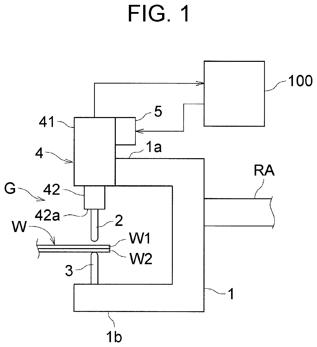
[0027]FIG. 1 is a schematic configuration view showing a spot welding gun G of the resistance spot welding apparatus used for the resistance spot welding method according to the embodiment.

[0028]The spot welding gun G includes, as main components: an upper electrode 2 that is mounted on an upper part 1a of a gun main body 1 held by a robot arm RA; a lower electrode 3 mounted on a lower part 1b of the gun main body 1; an electrically operated upper electrode lifting device (hereinafter referred to simply as an electrode lifting device) 4 that holds and moves up and down the upper electrode 2; and a current adjustment device 5 that...


PUM

PropertyMeasurementUnit
currentaaaaaaaaaa
pressureaaaaaaaaaa
electrical resistanceaaaaaaaaaa

Abstract

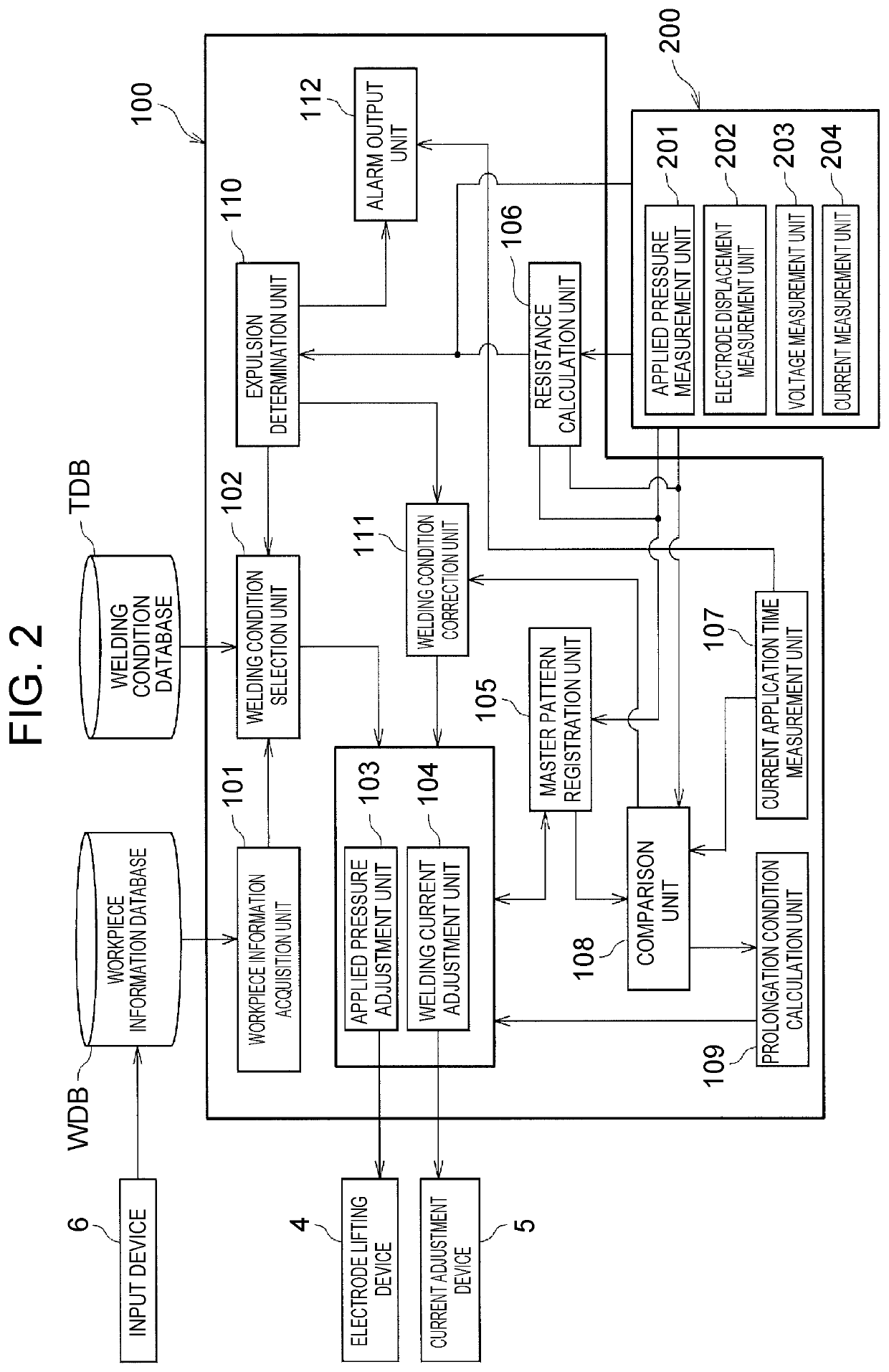
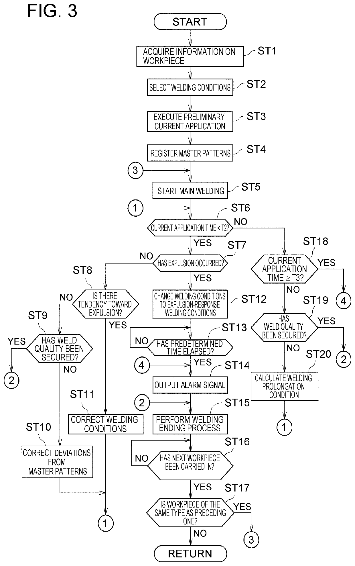
Provided are a method and an apparatus for resistance spot welding in which preliminary current application is executed and then main welding is executed in accordance with master patterns of various parameters obtained during the preliminary current application. The main welding is executed under welding conditions of the master patterns, and whether a welding abnormality has occurred and whether the welding abnormality is likely to occur are determined. When the welding abnormality is likely to occur, the welding conditions for the main welding are corrected so as to prevent the welding abnormality. When the welding abnormality is unlikely to occur, the welding conditions for the main welding are corrected so as to match the master patterns.

Description

INCORPORATION BY REFERENCE[0001]The disclosure of Japanese Patent Application No. 2018-042534 filed on Mar. 9, 2018 including the specification, drawings and abstract is incorporated herein by reference in its entirety.BACKGROUND1. Technical Field[0002]The present disclosure relates to a resistance spot welding method and a resistance spot welding apparatus. In particular, the present disclosure relates to improvement on a technique of executing preliminary current application and then executing main welding in accordance with master patterns of various parameters obtained during the preliminary current application.2. Description of Related Art[0003]Resistance spot welding is conventionally used as means for joining together a plurality of metal sheets in manufacturing a body frame of a vehicle. In resistance spot welding, a current is applied to a workpiece (a plurality of metal sheets) held between a pair of electrodes, and Joule heat generated due to the electrical resistance of ...

Claims


Application Information

Patent Timeline
Patent Type & Authority Patents(United States)
IPC IPC(8): B23K11/11B23K11/31B23K11/30
CPCB23K11/115B23K11/3009B23K11/314B23K11/11B23K11/36B23K11/255B23K11/253B23K11/258
Inventor NOMURA, KOJIOGURA, SHUHEIKAWAKITA, ATSUSHIKATO, NAOYAHIOKI, TORUFUKUSHIMA, KENJIKATO, SHUNGOTO, TAKASHI
Owner TOYOTA JIDOSHA KK
Learn More