Optical arrangement for the compensation of incorrect alignments of a reflector in relation to a light source
a technology of optical arrangement and light source, applied in the direction of lasers, laser construction details, spectrum investigation, etc., can solve the problems of further amplification, additional angular error between the incident laser beam and the reflected laser beam, and the ability of the retroreflector to move in a plan
Active Publication Date: 2022-02-15
METTLER TOLEDO GMBH
View PDF22 Cites 0 Cited by
- Summary
- Abstract
- Description
- Claims
- Application Information
AI Technical Summary
Benefits of technology
This arrangement ensures the spatial orientation of the optical axis remains stable despite changes in the reflector's position or orientation, enhancing beam alignment and positional stability in LASER systems.
Problems solved by technology
When a LASER resonator is designed with a large optical distance between reflectors delimiting the LASER resonator in order to achieve a desired beam quality, one of the challenges is to stabilize the reflectors in terms of their orientation in such a way that the LASER beam reflected by them is reflected onto itself.
With LASER interferometers, a similar problem arises, which is further amplified if a reflector which should reflect the LASER beam back onto itself is movable in the direction of a LASER beam and accordingly cannot be fastened rigidly to a mechanical structure.
In a cat's eye used as a retroreflector, an additional angular error occurs between the incident LASER beam and the reflected LASER beam, if the main axis of the cat's eye is tilted in relation to the optical axis of the incident LASER beam.
Due to the rigid pendulum, the ability of the retroreflector to move is limited to a plane.
Method used
View moreImage
Smart ImageViewing Examples

Examples
first embodiment
[0044]FIG. 4 shows a second reflector of an optical arrangement according to FIGS. 1 to 3 in a
second embodiment
[0045]FIG. 5 shows the second reflector in a second embodiment which is equally effective as the embodiment according to FIG. 4.
third embodiment
[0046]FIG. 6 shows the second reflector in a
Login to View More PUM
 Abstract
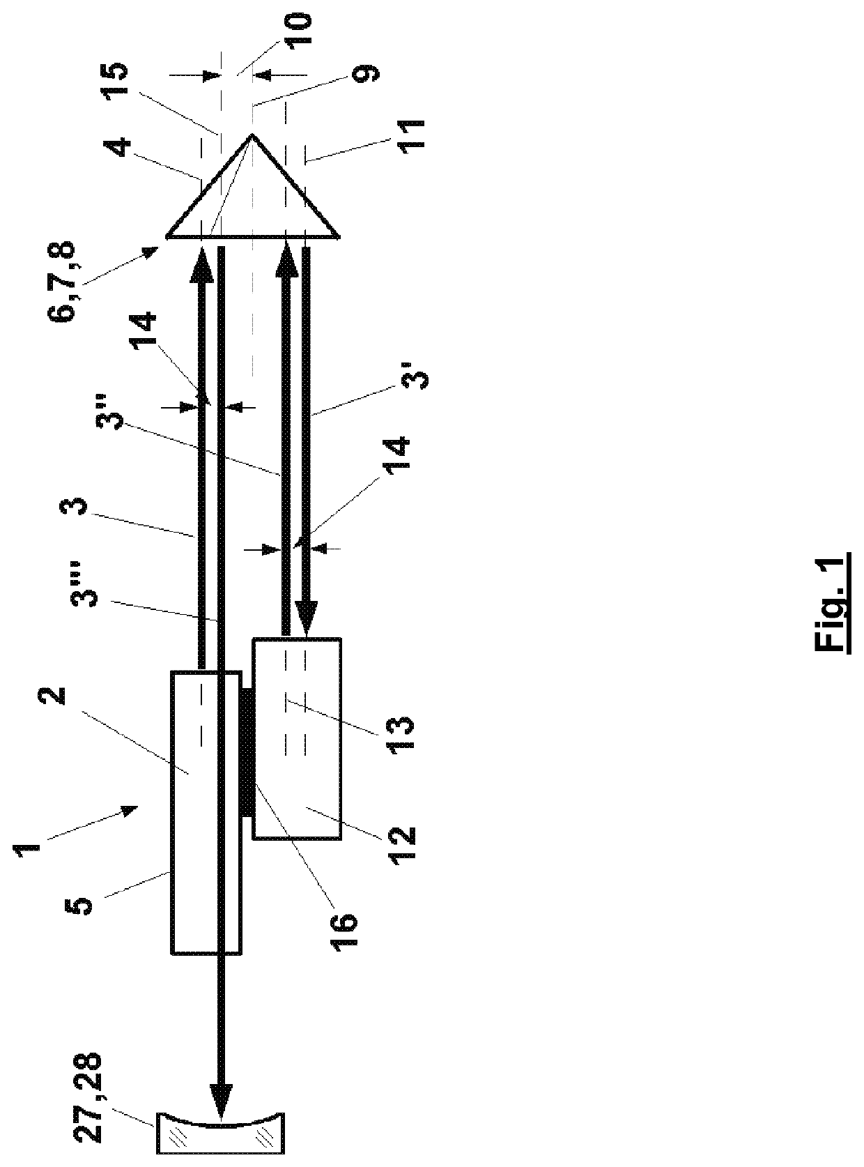
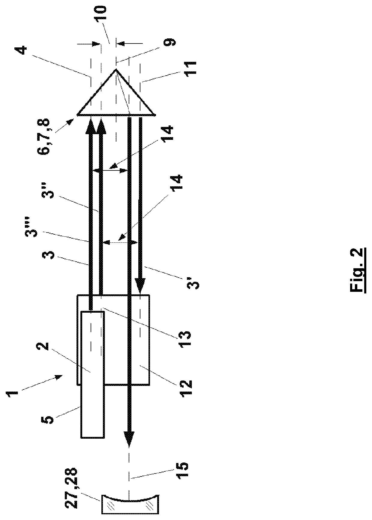
An optical arrangement has a light source, which emits a light beam along a first optical axis. A first reflector is provided, and a second reflector reflects light reflected by the first reflector. The first reflector has a transverse offset from the first optical axis to reflect light along a second optical axis which has a parallel offset of two times the transverse offset of the first optical axis. The second reflector reflects the light beam back to the first reflector along a third optical axis having a parallel offset with a fixed amount in a fixed transverse direction in relation to the second optical axis. The light beam is reflected by the first reflector along a fourth optical axis which has a parallel offset in relation to the first optical axis with a fixed amount counter to the fixed transverse direction.
Description
TECHNICAL FIELD OF THE INVENTION[0001]The invention relates to an optical arrangement having a light source, which emits a light beam in the direction of an optical axis, wherein the optical axis is defined in relation to a mechanical structure of the light source, having a first reflector for the light beam arranged at a distance from the light source and a second reflector for the light beam reflected by the first reflector.[0002]The optical arrangement can be part of a LASER resonator. It can also form part of a LASER interferometer or of a LASER spectrometer.BACKGROUND ART[0003]When a LASER resonator is designed with a large optical distance between reflectors delimiting the LASER resonator in order to achieve a desired beam quality, one of the challenges is to stabilize the reflectors in terms of their orientation in such a way that the LASER beam reflected by them is reflected onto itself. In many cases, there are no rigid mechanical structures to which the reflectors arranged...
Claims
Login to View More Application Information
Patent Timeline
 Patent Type & Authority Patents(United States)
IPC IPC(8): G01J3/26G01J3/453H01S3/08H01S3/081G01J3/42
CPCG01J3/26G01J3/4532H01S3/0813H01S3/08059G01J2003/423G01N21/031H01S3/086H01S3/094038H01S3/094084H01S3/025
Inventor KILLICH, FRANK
Owner METTLER TOLEDO GMBH
Features
- R&D
- Intellectual Property
- Life Sciences
- Materials
- Tech Scout
- Unparalleled Data Quality
- Higher Quality Content
- 60% Fewer Hallucinations
Learn More Browse by: Latest US Patents, China's latest patents, Technical Efficacy Thesaurus, Application Domain, Technology Topic, Popular Technical Reports.
© 2025 PatSnap. All rights reserved.Legal|Privacy policy|Modern Slavery Act Transparency Statement|Sitemap|About US| Contact US: help@patsnap.com