Wireless charging apparatus

a charging apparatus and wireless charging technology, applied in electric power, electric vehicles, transportation and packaging, etc., can solve the problems of slow charging and reducing power transfer, and achieve the effects of increasing power transfer, reducing power transfer, and improving wireless charging capabilities of mobile devices

Active Publication Date: 2022-02-15
HARRIS GEOFFREY HERBERT
View PDF9 Cites 1 Cited by
  • Summary
  • Abstract
  • Description
  • Claims
  • Application Information

AI Technical Summary

Benefits of technology

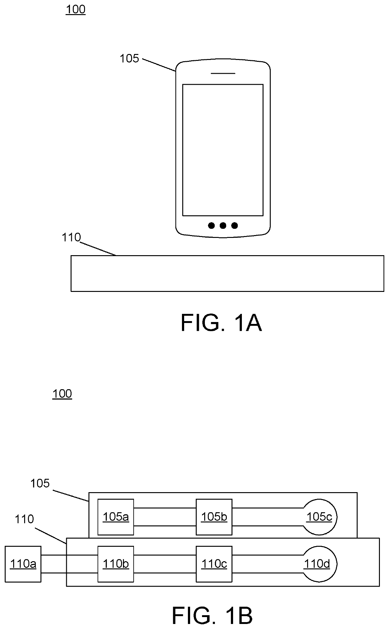
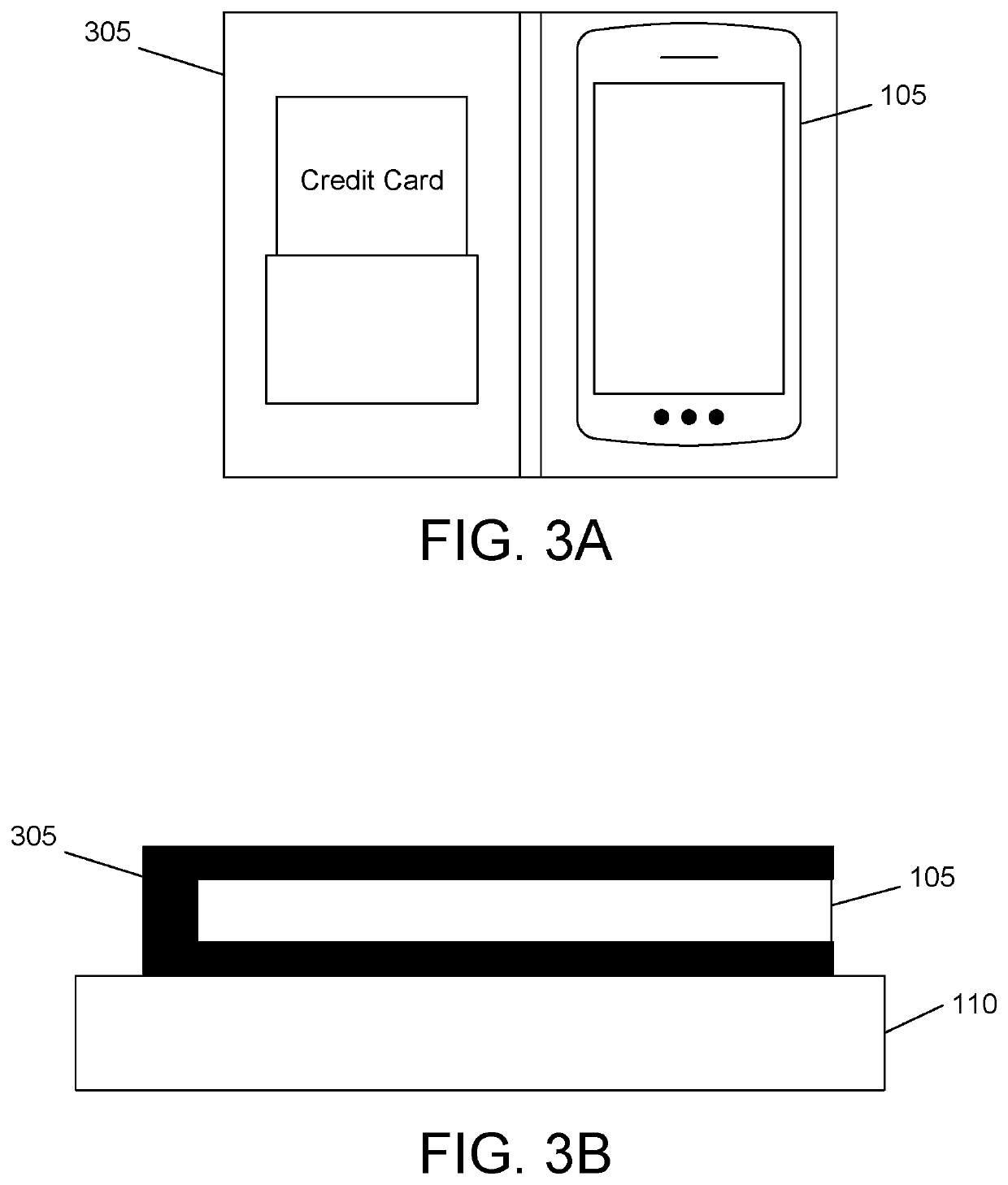
[0005]To overcome limitations in the prior art described above, and to overcome other limitations that will be apparent upon reading and understanding the present specification, aspects described herein are directed to apparatuses and systems for improving wireless charging capabilities of mobile devices stored in various enclosures.
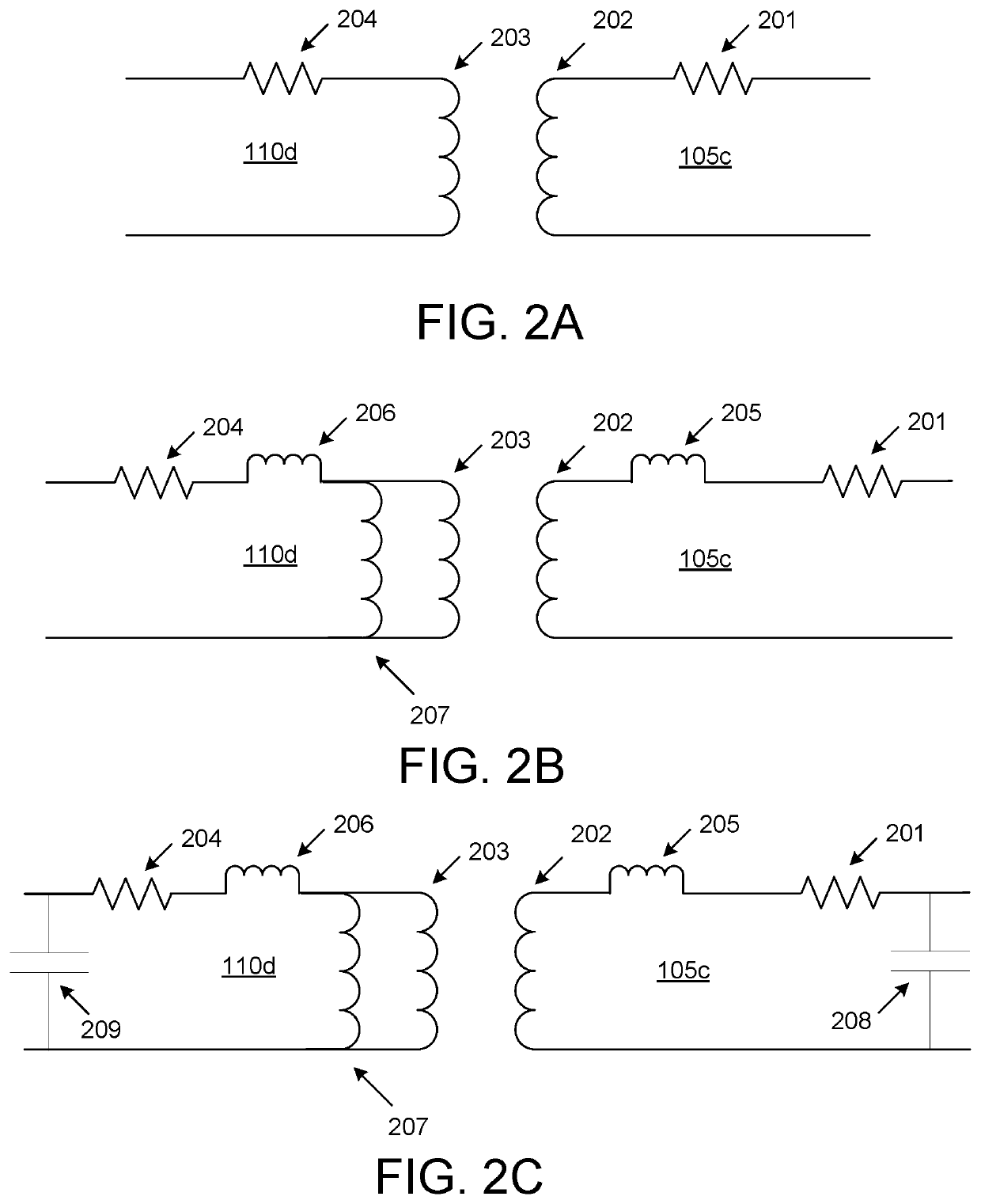
[0006]A first aspect described herein provides a first electrical coil configured to establish a first wireless coupling with a transmitter coil of a power supply. The first aspect described herein also provides a second electrical coil configured to establish a second wireless coupling with the first electrical coil and to establish a third wireless coupling with a receiver coil of a mobile device. In one or more instances, a distance between the receiver coil and the transmitter coil may exceed a range over which the transmitter coil is able to transfer power to the receiver coil via a single wireless coupling between the transmitter coil and the receiver coil. Additionally or alternatively, the distance between the receiver coil and the transmitter coil may diminish power transfer between the transmitter coil and the receiver coil (e.g., cause slower charging). In one or more instances, the first wireless coupling, the second wireless coupling, and the third wireless coupling, when established, may enable the transmitter coil to perform a wireless power transfer to the receiver coil. Additionally or alternatively, the first wireless coupling, the second wireless coupling, and the third wireless coupling, when established, may increase the power transfer between the transmitter coil and the receiver (e.g., cause faster charging).
[0009]In one or more instances, wireless power transfer via the first wireless coupling, the second wireless coupling, and the third wireless coupling may improve the power transfer and / or efficiency of the power transfer relative to that of a direct coupling between the transmitter coil and the receiver coil. As a result, by implementing the first electrical coil and the second electrical coil, the charging time of a battery may be reduced.

Problems solved by technology

Additionally or alternatively, the distance between the receiver coil and the transmitter coil may diminish power transfer between the transmitter coil and the receiver coil (e.g., cause slower charging).

Method used


Image

  • Wireless charging apparatus
  • Wireless charging apparatus
  • Wireless charging apparatus

Examples


Embodiment Construction

[0025]In the following description of the various embodiments, reference is made to the accompanying drawings, which illustrate various embodiments in which aspects described herein may be practiced. It is to be understood that other embodiments may be utilized and structural and functional modifications may be made without departing from the scope of the described aspects and embodiments. Aspects described herein are capable of other embodiments and of being practiced or being carried out in various ways. Also, it is to be understood that the phraseology and terminology used herein are for the purpose of description and should not be regarded as limiting. Rather, the phrases and terms used herein are to be given their broadest interpretation and meaning. The use of “including” and “comprising” and variations thereof is meant to encompass the items listed thereafter and equivalents thereof as well as additional items and equivalents thereof. The use of the terms “mounted,”“connected...


PUM


Abstract

Apparatuses and systems are provided for improving wireless power transmission for mobile devices. An enclosure for a mobile device may include a first electrical coil configured to establish a first wireless coupling with a transmitter coil of a power supply and a second electrical coil configured to establish a second wireless coupling with the first electrical coil and to establish a third wireless coupling with a receiver coil of a mobile device. A distance between the receiver coil and the transmitter coil may exceed a range over which the transmitter coil may be able to transfer power to the receiver coil via a single wireless coupling between the transmitter coil and the receiver coil. The first wireless coupling, the second wireless coupling, and the third wireless coupling, when established, may enable the transmitter coil to perform a wireless power transfer to the receiver coil.

Description

FIELD[0001]Aspects described herein generally relate to wireless power transmission in mobile devices. More specifically, aspects relate to improving wireless charging capabilities of various mobile device enclosures.BACKGROUND[0002]The use of magnetic induction in wireless charging of mobile devices is conventional. In many instances, an enclosure (e.g., a case, wallet, or the like) may be placed over the mobile device for protection. However, use of an enclosure may limit wireless charging capabilities with mobile devices.[0003]Accordingly, there exists a need for ways to improve wireless charging capabilities for mobile devices that are stored in such enclosures.BRIEF SUMMARY[0004]The following presents a simplified summary of various aspects described herein. This summary is not an extensive overview, and is not intended to identify key or critical elements or to delineate the scope of the claims. The following summary merely presents some concepts in a simplified form as an int...

Claims


Application Information

Patent Timeline
Patent Type & Authority Patents(United States)
IPC IPC(8): H02J7/02H02J50/12H02J50/00H02J50/50
CPCH02J7/025H02J50/005H02J50/12H02J50/50H02J7/0044H02J7/02
Inventor HARRIS, GEOFFREY HERBERTELLSTEIN, DAVID
Owner HARRIS GEOFFREY HERBERT
Why Eureka
Try Eureka