Parallel optical fiber transceiver module

a transceiver module and parallel technology, applied in the field of optical modules, can solve the problems of reducing the number of transceiver ports which can be achieved within a limited module width, unable to meet the transmission bandwidth and distance requirements of traditional electronic interconnection technology, and large amounts of data exchange between servers, so as to ensure the coupling efficiency of optical signals, and reduce the number of transceiver ports. achieve the effect of ensuring alignment tolerance and relatively low position

Active Publication Date: 2022-02-22
SENKO ADVANCED COMPONENTS
View PDF23 Cites 0 Cited by
  • Summary
  • Abstract
  • Description
  • Claims
  • Application Information

AI Technical Summary

Benefits of technology

[0008]The purpose of the invention is to provide a parallel optical fiber transceiver module, which is used in a parallel optical fiber transmission system to increase the alignment density of the optical fiber ports and satisfy the technical requirements of the large data center and supercomputer system on high-density optical fiber interconnection.
[0011]Considering the technical requirements of the parallel optical fiber transceiver module, this invention proposes a positioning substrate with both sides etched, and the two-dimensional optical fiber array fabricated based on this substrate can ensure positioning accuracy between the optical fibers in the same row, but the positioning accuracy between the two rows of optical fibers is relatively low. At the time of coupling and alignment, priority shall be given to assurance of alignment accuracy between one row of optical fibers and the laser array, while the alignment accuracy between the other row of optical fibers and the photodetector is somewhat lower; however, as described above, as the alignment tolerance of the receiving light path is larger, the coupling efficiency of optical signal can still be ensured.
[0012]Compared with the prior art, the invention has the following beneficial effects: Through the double-sided exposure technology in the microelectronic process, a mask pattern is made on both sides of a piece of quartz glass, and then a high-precision optical fiber positioning slot array is etched through the chemical etching process. The double-exposure photoetching machine in the microelectronic process can ensure that the mask pattern on the same side has a high positioning accuracy, and the positioning accuracy is relatively low between the patters on the two sides, but there is still sufficient accuracy to meet the technical requirements of the parallel optical fiber transceiver module.

Problems solved by technology

Large amounts of data exchange are required between servers.
The traditional electronic interconnection technology can not satisfy the transmission bandwidth and distance requirements, so parallel optical fiber interconnection technology is widely used in the data center.
With respect to the existing parallel optical fiber transceiver modules, the first solution is that the laser array and the photodetector array are mounted in a linear array, and aligned with a one-dimensional optical fiber array; its advantage is that the manufacturing process of the one-dimensional optical fiber array is relatively simple, and its disadvantage is that the number of transceiver ports which can be achieved is reduced by half within a limited module width, thus not satisfying the market demand for high-density parallel interconnection.
The second solution is that the laser array and the photodetector array are mounted in two rows, and coupled and aligned with two one-dimensional optical fiber arrays respectively; this method can increase the number of transceiver ports within a limited width, but its disadvantage is that two one-dimensional optical fiber arrays are stacked together, thus increasing the thickness of the transceiver module.

Method used


Image

  • Parallel optical fiber transceiver module

Examples


Embodiment Construction

[0019]The technical solution of the patent is further described in detail below in combination with the specific embodiments.

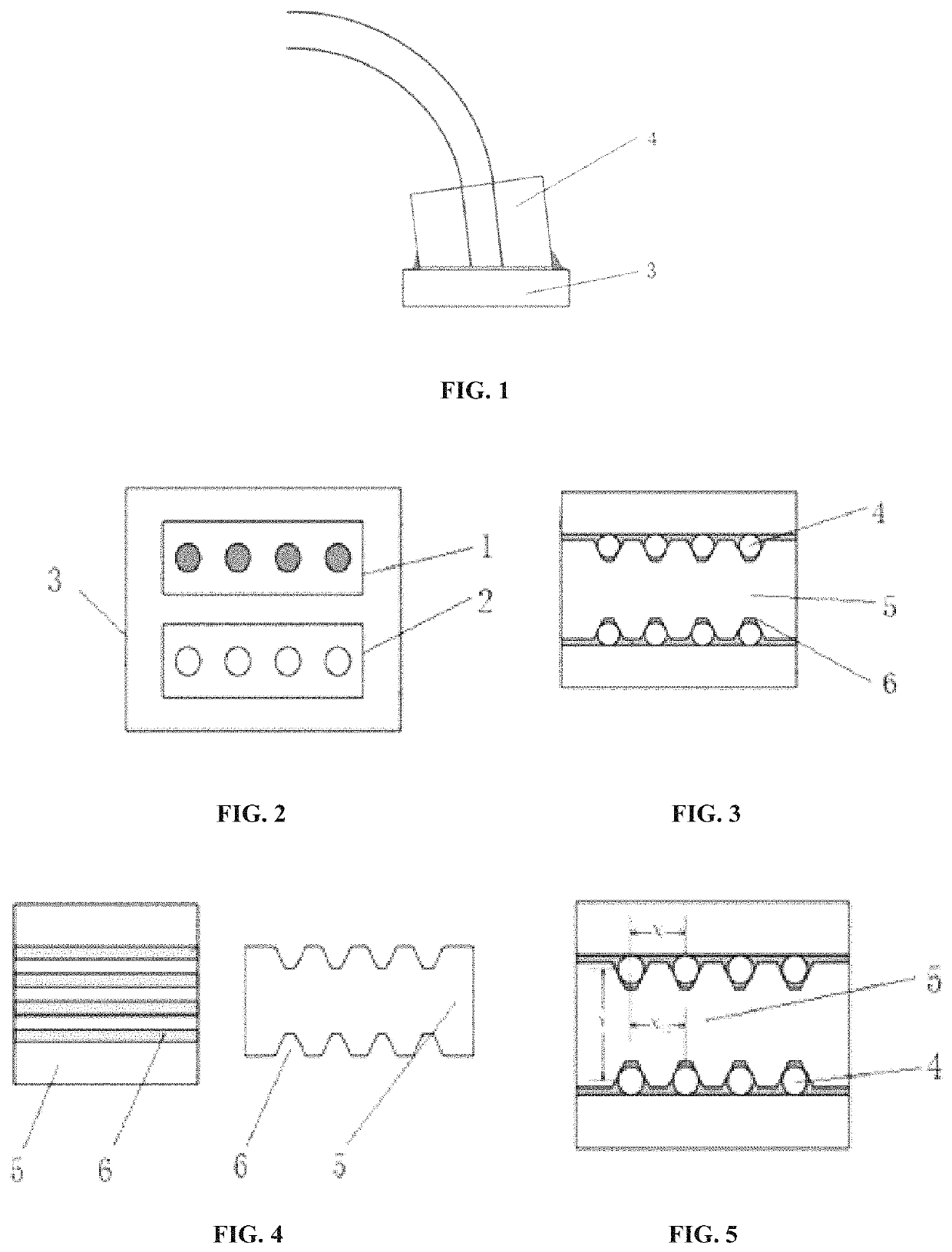
[0020]As shown in FIG. 1, the optical fiber transceiver module of this invention comprises a driving circuit board 3 on which a laser array 1 and a photodetector array 2 are mounted, a two-dimensional optical fiber array 4, and the two-dimensional optical fiber array 4 is coupled and aligned with the laser array 1 and the photodetector array 2, and glue is used for fixing.

[0021]The laser array 1 and the photodetector array 2 are mounted in two rows on the driving circuit board 3, as shown in FIG. 2. The two-dimensional optical fiber array 4 is fabricated based on a positioning substrate 5 with both sides etched, whose end face is shown in FIG. 3. The two-dimensional optical fiber array 4 is arranged in two rows, whose spacing correspond respectively to spacing of the laser array 1 and spacing of the photodetector array 2 in FIG. 2.

[0022]The positioning substra...


PUM

PropertyMeasurementUnit
diameteraaaaaaaaaa
thicknessaaaaaaaaaa
spacing distanceaaaaaaaaaa

Abstract

This invention discloses a parallel optical fiber transceiver module, comprising a laser array, a photodetector array, a driving circuit board and a two-dimensional optical fiber array; the laser array and the photodetector array are mounted in two rows on the driving circuit board, and aligned and coupled with two rows of optical fibers in the fiber array respectively, and glue is used for fixing; the two-dimensional optical fiber array is fabricated on a positioning substrate with both sides etched; the invention has the following beneficial effects: through the double-sided exposure technology in the microelectronic process, a mask pattern is made on both sides of a piece of quartz glass, and then a high-precision optical fiber positioning slot array is etched through the chemical etching process. The double-exposure photoetching machine in the microelectronic process can ensure that the mask pattern on the same side has a high positioning accuracy, thus meeting the technical requirements of the parallel optical fiber transceiver module.

Description

CROSS-REFERENCE TO RELATED APPLICATIONS[0001]The present application is a national phase application of PCT / CN2017 / 089551 which claims priority to Chinese Patent Application No. 201620634613.5 filed Jun. 24, 2016, the disclosure of which is incorporated by reference herein.COPYRIGHT NOTICE[0002]A portion of the disclosure of this patent document contains material, which is subject to copyright protection. The copyright owner has no objection to the facsimile reproduction by anyone of the patent document or the patent disclosure, as it appears in the Patent and Trademark Office patent file or records, but otherwise reserves all copyright rights whatsoever.FIELD OF THE INVENTION[0003]This invention relates to an optical module used in the field of optical fiber technology, particularly to a parallel optical fiber transceiver module used in the parallel optical fiber transmission system.BACKGROUND[0004]With the advent of the big data era, large data centers have seen rapid growth. Data...

Claims


Application Information

Patent Timeline
Patent Type & Authority Patents(United States)
IPC IPC(8): G02B6/42
CPCG02B6/423G02B6/42G02B6/4239G02B6/4246G02B6/4249G02B6/3664
Inventor YANG, KAIFA
Owner SENKO ADVANCED COMPONENTS
Why Eureka
Try Eureka