Acoustic filter with attenuation control

a technology of attenuation control and filter, applied in the field of acoustic filters, can solve problems such as irritated ears

Active Publication Date: 2022-03-08
SONOVA AG
View PDF12 Cites 1 Cited by
  • Summary
  • Abstract
  • Description
  • Claims
  • Application Information

AI Technical Summary

Benefits of technology

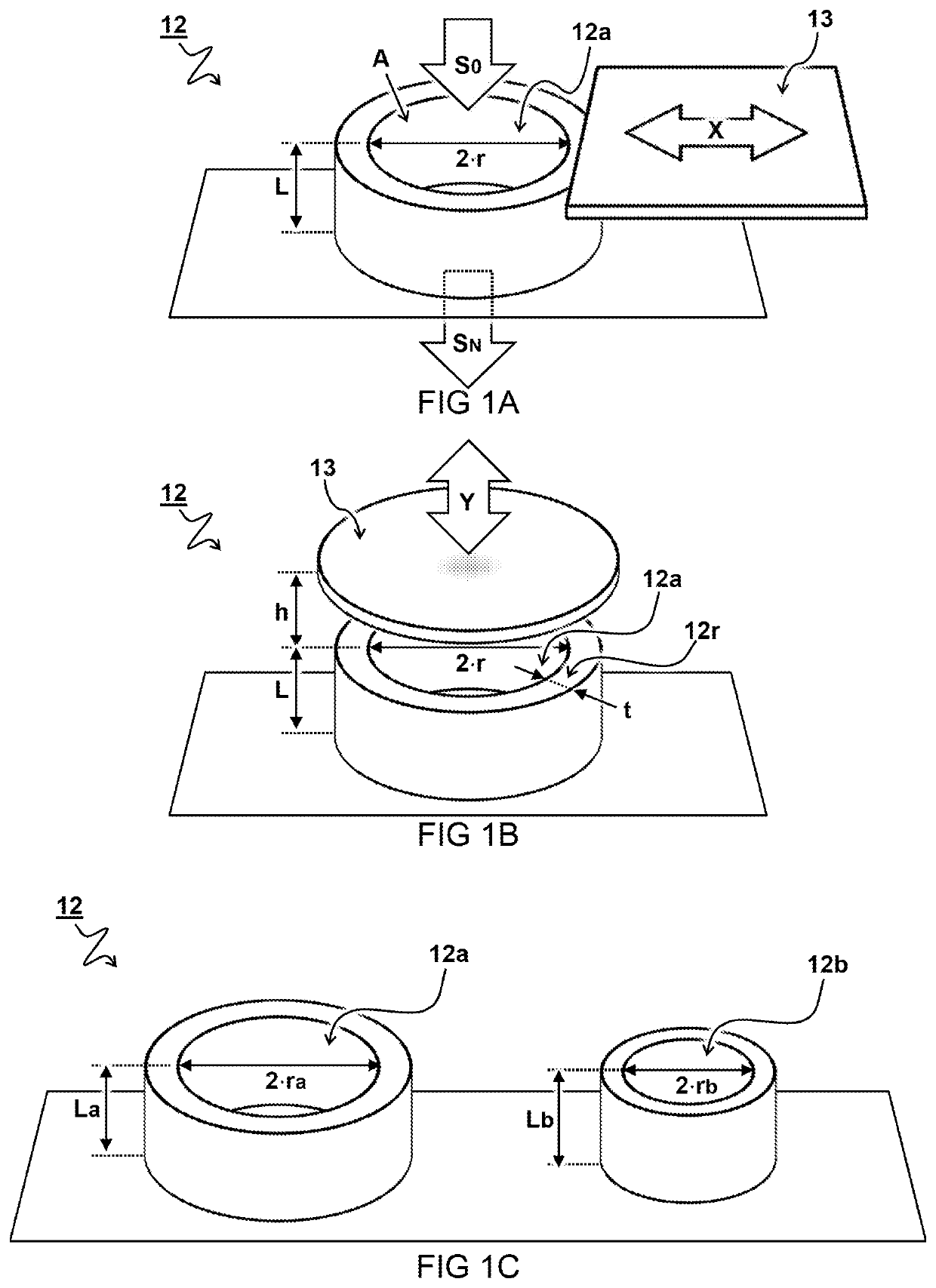
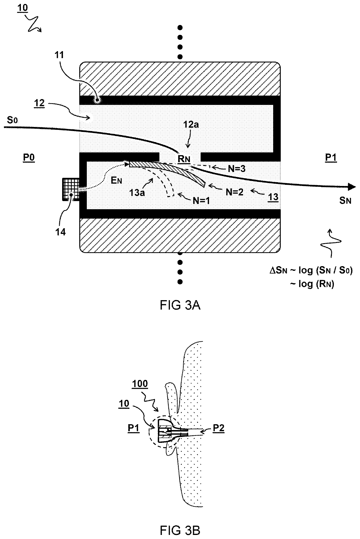
[0006]Aspects of the present disclosure relate to an acoustic filter and earplug comprising the filter. In preferred embodiments, the acoustic filter comprises a filter housing. Typically, the acoustic filter or housing is placeable or integrated in an earplug. In this way a seal is formed between an auditory canal of an ear and an external surroundings. A sound passage may extend through the filter for receiving sound from the external surroundings and transmitting the sound into the auditory canal. The sound passage can have one or more apertures. The passage and apertures can provide an acoustic resistance for the sound received and transmitted there through. In preferred embodiments, the filter comprises a valve system with one or more acoustic valves arranged in the sound passage. The valves may control the acoustic resistance of the one or more apertures e.g. based on a control signal. In this way an attenuation of a sound pressure level of the transmitted sound can be selected.
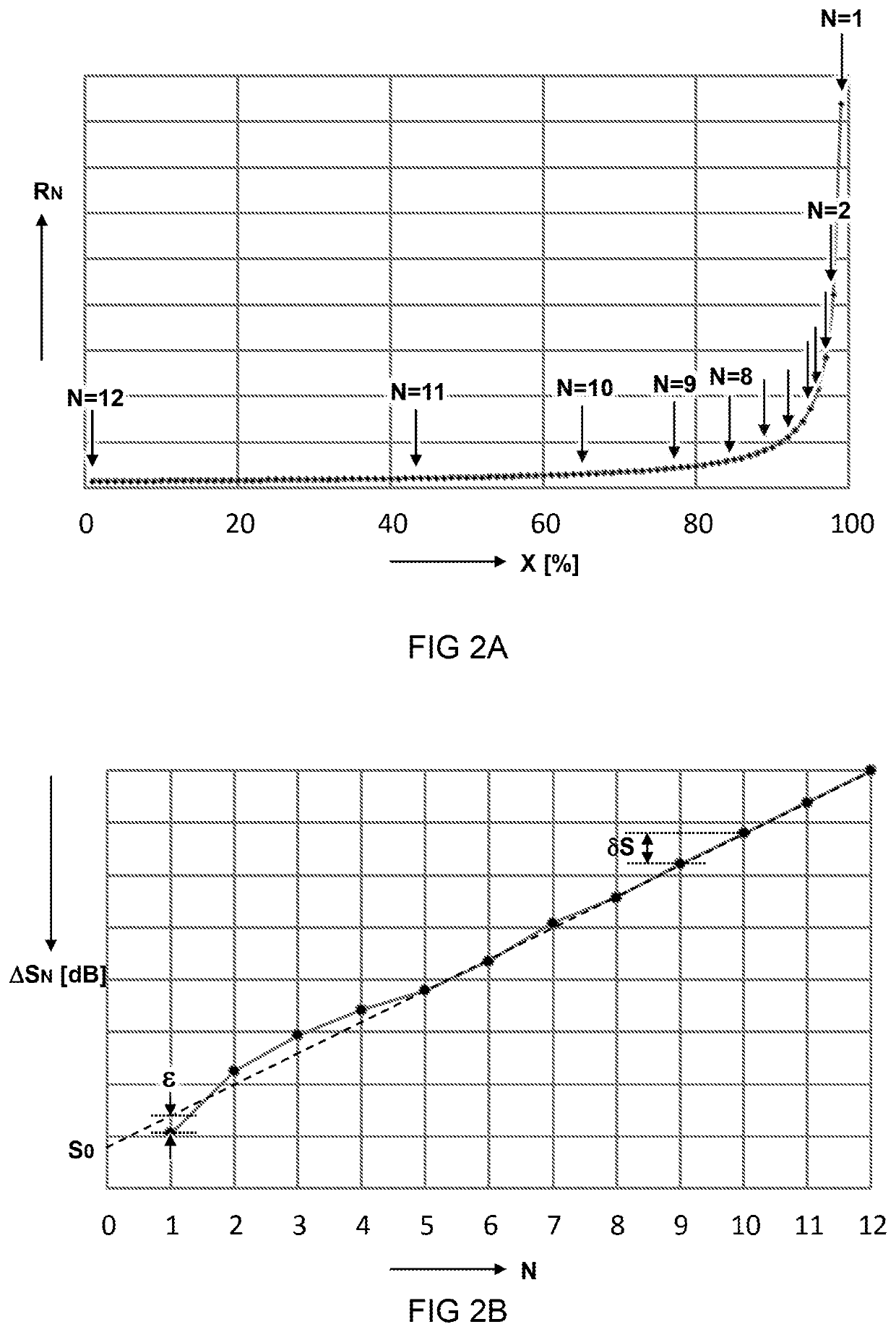
[0008]It is recognized that attenuating the sound pressure level on a logarithmic scale, may better conform to human hearing and thus improve desired control over the sound level. While conventional volume control may be realized by an electronic sound generator, the inventors find that improved control of ambient volume can be achieved using a preselected range of acoustic resistances which may not require electronic conversion of the sound. In some embodiments, the attenuation control may be improved by using multiple valves and / or adapted aperture shapes. For example, the tuning of acoustic resistances can be improved by combining predetermined aperture sizes that are selectively opened or closed. Additionally, or alternatively, partially opened valves can be used to provide intermediate acoustic properties. By shaping the aperture and / or valve, the open area can be more accurately determined.

Problems solved by technology

Furthermore, prolonged use may lead to irritated ears, as the ears are not ventilated.

Method used


Image

  • Acoustic filter with attenuation control
  • Acoustic filter with attenuation control
  • Acoustic filter with attenuation control

Examples


Embodiment Construction

[0020]Terminology used for describing particular embodiments is not intended to be limiting of the invention. As used herein, the singular forms “a”, “an” and “the” are intended to include the plural forms as well, unless the context clearly indicates otherwise. The term “and / or” includes any and all combinations of one or more of the associated listed items. It will be understood that the terms “comprises” and / or “comprising” specify the presence of stated features but do not preclude the presence or addition of one or more other features. It will be further understood that when a particular step of a method is referred to as subsequent to another step, it can directly follow said other step or one or more intermediate steps may be carried out before carrying out the particular step, unless specified otherwise. Likewise it will be understood that when a connection between structures or components is described, this connection may be established directly or through intermediate stru...


PUM


Abstract

An acoustic filter including a valve system with acoustic valves arranged in a sound passage for controlling the acoustic resistance of respective apertures based on a control signal for selecting an attenuation of a sound pressure level of transmitted sound compared to that of received sound. The acoustic filter is adapted to provide the selection of the attenuation from a sequence of predetermined attenuations based on a selection of the control signal. Each attenuation in the sequence corresponds to acoustic valves providing the apertures with a respective predetermined acoustic resistance, wherein the acoustic resistances of subsequent attenuations in the sequence are adapted to correspond with a linear increase or decrease in the attenuation of the sound in decibels.

Description

CROSS-REFERENCE TO RELATED APPLICATIONS[0001]This application is the U.S. National Stage of PCT / NL2019 / 050043, filed Jan. 25, 2019, which claims priority to: Netherlands Patent Application No. 2020330, filed Jan. 26, 2018, the entire contents of both of which are herein incorporated by reference in their entireties.TECHNICAL FIELD AND BACKGROUND[0002]The present disclosure relates to an acoustic filter for attenuating sound in an earplug, a method for manufacturing the acoustic filter, and use of the acoustic filter.[0003]Various products like hearables, hearing aids, earphones, and headphones can provide an acoustical seal to the ear. Wearing such product may give the user a feeling of being occluded and cut off from their surroundings. Furthermore, prolonged use may lead to irritated ears, as the ears are not ventilated. Hence some of these products may include an ambient channel or sound passage to provide an open (acoustical) pathway through the otherwise sealed housing. Typical...

Claims


Application Information

Patent Timeline
Patent Type & Authority Patents(United States)
IPC IPC(8): H04R25/00A61F11/08H04R1/10
CPCA61F11/08H04R1/1016H04R1/1041H04R25/652H04R25/658A61F2011/085A61F2240/001H04R2225/025H04R2225/61H04R2460/11A61F2250/0004A61F11/085
Inventor VAN 'T HOF, PIETER GERARDLARA-QUINTANILLA, ADRIÁNWILMINK, ENGBERT
Owner SONOVA AG
Why Eureka
Try Eureka