
Electronic device including phase locked loop circuit used for radio frequency communication

a phase lock loop and electronic device technology, applied in the direction of pulse automatic control, transmission monitoring, electrical apparatus, etc., can solve the problems of component damage of electronic device, power amplifier circuit damage, etc., to prevent component damage in electronic device

Active Publication Date: 2022-03-08
SAMSUNG ELECTRONICS CO LTD
View PDF14 Cites 0 Cited by
  • Summary
  • Abstract
  • Description
  • Claims
  • Application Information

AI Technical Summary

Benefits of technology

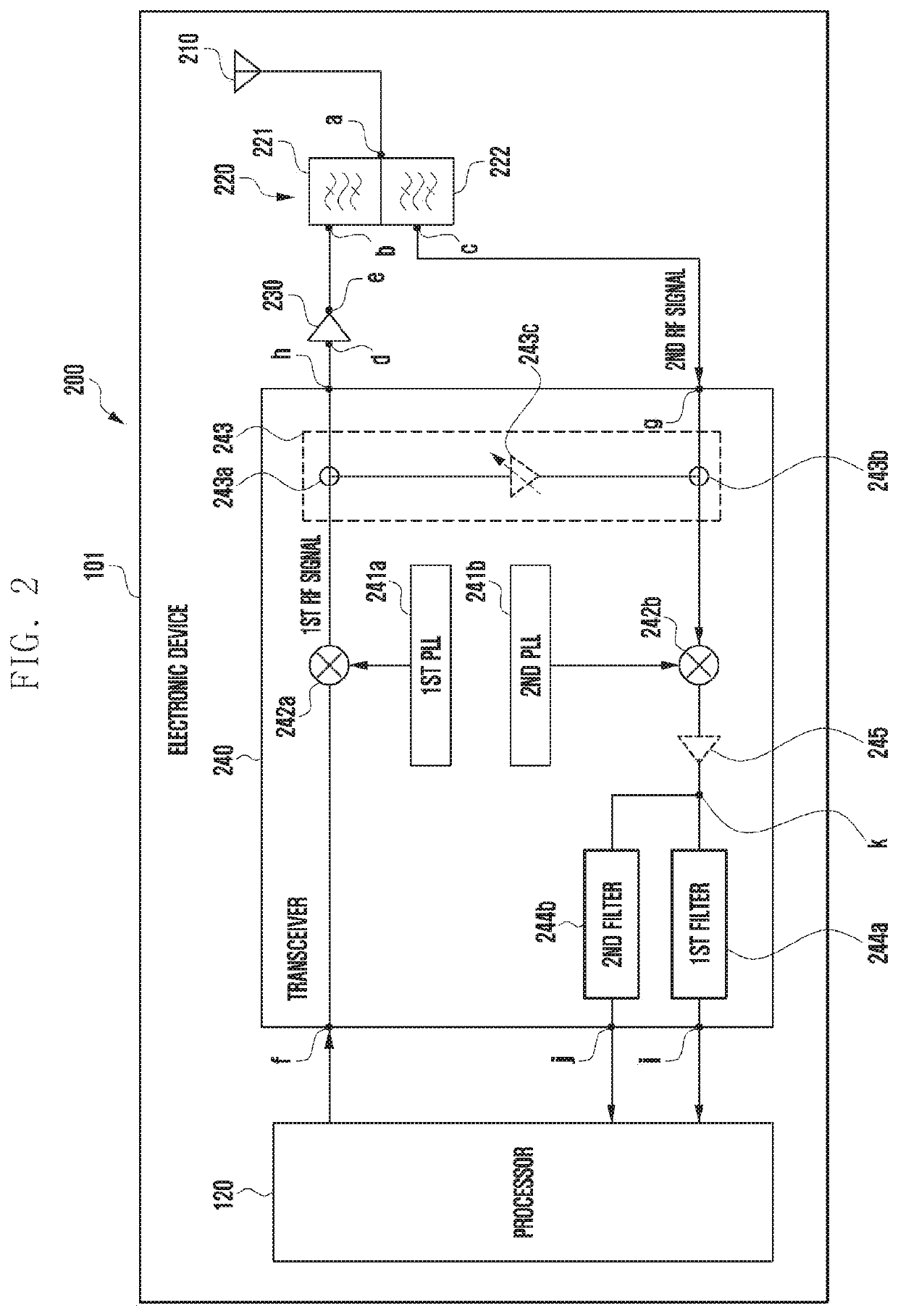
[0011]Aspects of the disclosure are to address at least the above-mentioned problems and / or disadvantages and to provide at least the advantages described below. Accordingly, an aspect of the disclosure is to provide an electronic device configured to determine whether a PLL circuit is operating normally, thereby preventing component damage in the electronic device.

Problems solved by technology

This may cause components of the electronic device to be damaged or cause the connection between the electronic device and the network to be dropped.
For example, due to the abnormal operation of the PLL circuit, an RF signal amplified by a power amplifier circuit may be reflected toward the power amplifier circuit without passing through a duplexer, thereby causing the power amplifier circuit to be damaged.
Thus, connection for a communication service, such as a call service, tends to frequently drop.
However, this method tends to reflect incorrect operations.
In addition, due to a phenomenon in which the impedance of the antenna is distorted, the acquired power may be lower than the reference value despite the normal operation of the PLL circuit.
Therefore, it may be mistakenly recognized that the PLL circuit operates abnormally.
In this case, an error may occur in determining the normal or abnormal operation.

Method used


Image

  • Electronic device including phase locked loop circuit used for radio frequency communication
  • Electronic device including phase locked loop circuit used for radio frequency communication
  • Electronic device including phase locked loop circuit used for radio frequency communication

Examples


first embodiment

[0087]FIG. 7 illustrates operations 700 of the processor 120 according to a

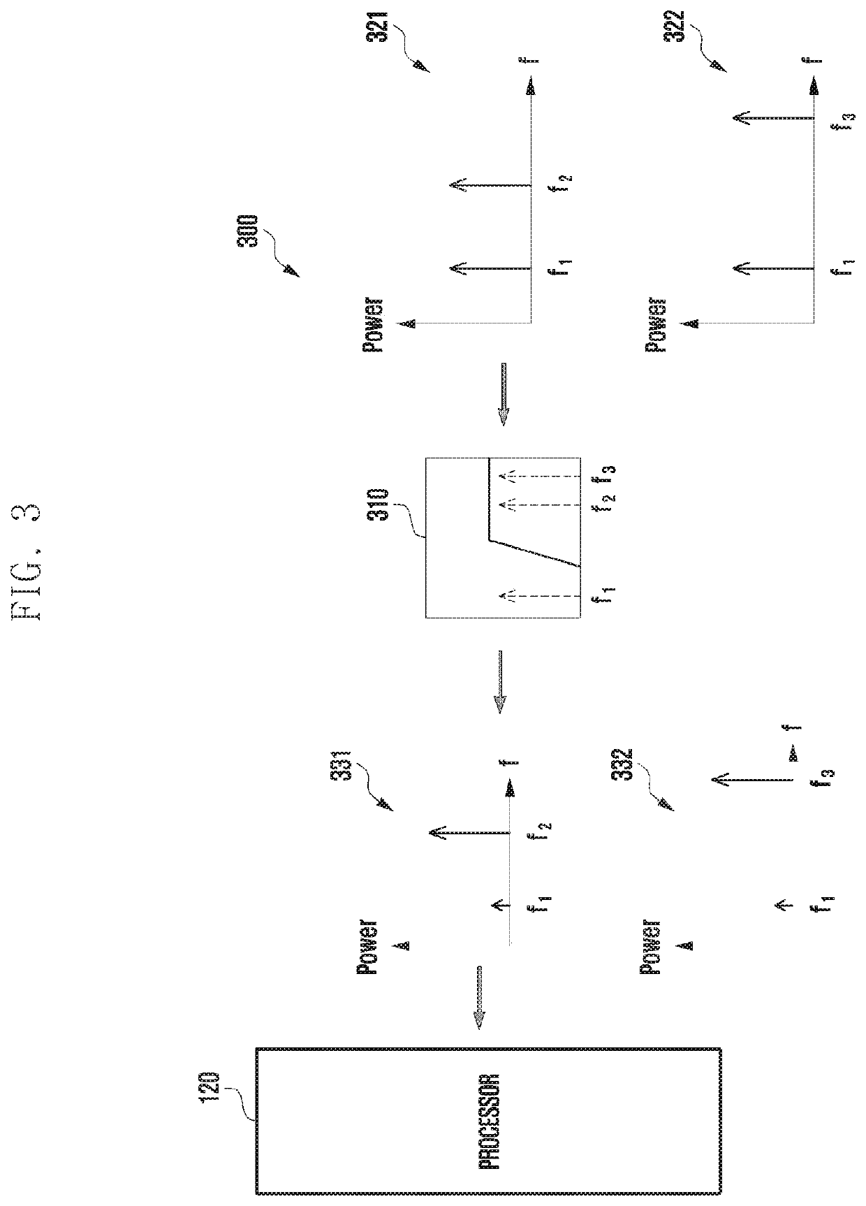
[0088]Referring to FIG. 7, in step 710, the processor 120 may identify a frequency band having power greater than or equal to a specified level in a signal received from the HPF through the third output port of the transceiver.

[0089]In step 720, the processor 120 may recognize that the identified frequency band is different from the first reference value.

[0090]In step 730, the processor may reset the transceiver in accordance with to the above recognition. For example, the processor may reset the frequency of a signal to be outputted from the first PLL circuit.

second embodiment

[0091]FIG. 8 illustrates operations 800 of the processor 120 according to a

[0092]Referring to FIG. 8, in step 810, the processor may calculate the amount of power of a signal received from a notch filter through the third output port of the transceiver.

[0093]In step 820, the processor may recognize that the calculated intensity exceeds the second reference value.

[0094]In step 830, the processor may reset the transceiver 240 in accordance with the above recognition.

third embodiment

[0095]FIG. 9 illustrates operations 900 of the processor 120 according to a

[0096]Referring to FIG. 9, in step 910, the processor may calculate the amount of power of a signal received from an LPF through the third output port of the transceiver.

[0097]In step 920, the processor may recognize that the calculated intensity is less than the third reference value.

[0098]In step 930, the processor may reset the transceiver 240 in accordance with the above recognition.

[0099]According to an embodiment, an electronic device may include an antenna, a duplexer including a first BPF outputting a first RF signal of a transmission frequency band designated to be used for data transmission to a network through the antenna, and a second BPF configured to output a second RF signal of a reception frequency band designated to be used for data reception from the network through the antenna, a power amplifier circuit configured to amplify the first RF signal and output the amplified signal to the first B...


PUM


Abstract

Disclosed is an electronic device that is configured to determine whether a phase locked loop (PLL) circuit is operating normally, thereby preventing component damage in the electronic device and preventing disconnection from a communication network.

Description

CROSS-REFERENCE TO RELATED APPLICATION(S)[0001]This application is based on and claims priority under 35 U.S.C. § 119 to Korean Patent Application No. 10-2019-0117080, filed on Sep. 23, 2019, in the Korean Intellectual Property Office, the disclosure of which is incorporated herein by reference in its entirety.BACKGROUND1. Field[0002]The disclosure relates generally to an electronic device, and more particularly, to an electronic device including a phase locked loop (PLL) circuit in radio frequency (RF) communication.2. Description of Related Art[0003]An electronic device may transmit, through an antenna, an RF signal in a frequency band designated for use in cellular communication, such as 5th generation (5G) or legacy communication. A PLL circuit is capable of locking a frequency band of a reference signal used when converting a baseband signal into an RF signal, to a designated reference frequency band.[0004]When the PLL circuit operates abnormally, a phenomenon in which the freq...

Claims


Application Information

Patent Timeline
Patent Type & Authority Patents(United States)
IPC IPC(8): H03L7/093H03L7/185
CPCH03L7/093H03L7/185H04B1/0057H04B1/40H04B1/50H04B17/318H04B17/101
Inventor LEE, YOUNGMINKIM, WOOJINNA, HYOSEOK
Owner SAMSUNG ELECTRONICS CO LTD
Learn More