Door system with a deceleration mechanism

a technology of deceleration mechanism and door system, which is applied in the direction of door/window fittings, transportation and packaging, and wing accessories, etc., can solve the problems of coupling mechanism failure, rapid pressure drop in the cockpit, and neither of these solutions describe a deceleration mechanism, etc., to achieve simple and light-weight design, less failure sources, and easy installation

Active Publication Date: 2022-03-15
AIRBUS HELICOPTERS DEUT GMBH
View PDF16 Cites 2 Cited by
  • Summary
  • Abstract
  • Description
  • Claims
  • Application Information

AI Technical Summary

Benefits of technology

[0012]Based on the limitations and drawbacks of the prior art, an objective is to provide a door system for controlling an opening of a door that separates compartments of an aircraft, and that comprises a door panel and a deceleration mechanism. The door system should enable a controlled opening of the door when the air pressure difference between the area that is separated by the door exceeds a predetermined threshold. The door system should have a simple and light-weight design, have less failure sources than current door systems, and be easy to install. The deceleration mechanism should be fast, reliable, and operate without a coupling mechanism.
[0016]The carpet may continue to be folded during the opening of the door module and decelerate the rotational movement of the door panel. Therefore, the carpet may need a predetermined construction or a predetermined attachment in order to provide a reliable folding in this area.
[0017]As a result, the door system may have less failure sources than conventional door systems. The deceleration mechanism may be simply installed and require a low maintenance effort while providing a fast and reliable activation of the deceleration function. Furthermore, the system is well suited for retrofitting and a coupling mechanism may be omitted.

Problems solved by technology

For example, a bird may strike and break a cockpit window causing such a rapid pressure drop in the cockpit.
However, neither of these solutions describe a deceleration mechanism that decelerates an opening of a door panel in case of a rapid decompression case.
These solutions involve additional potential failure sources.
For example, the coupling mechanism may fail in case of an emergency.
Moreover, deceleration systems with a coupling mechanism are often complicated and heavy.

Method used


Image

  • Door system with a deceleration mechanism
  • Door system with a deceleration mechanism
  • Door system with a deceleration mechanism

Examples


Embodiment Construction

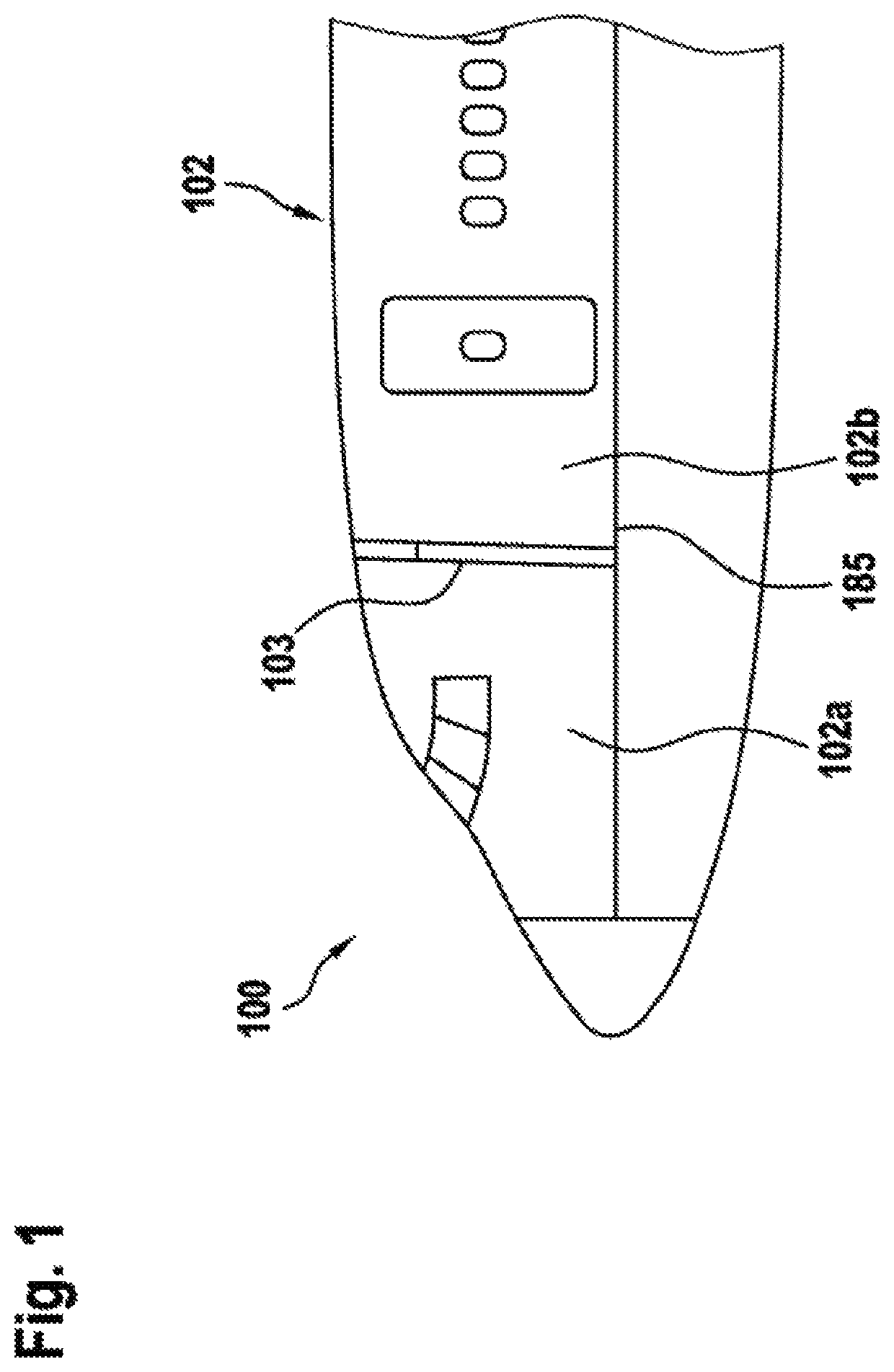
[0040]Exemplary embodiments may be included in any vehicle with a door that separates two pressurized compartments, and in which a rapid change in pressure in only one of the compartments would compromise the structural integrity of the vehicle. Examples of such vehicles may include aircrafts such as airplanes, multicopters, helicopters, drones, etc.

[0041]FIG. 1 shows an example of a vehicle 100. As shown in FIG. 1, vehicle 100 may be an aircraft, and, more particularly, an airplane. Aircraft 100 is exemplarily embodied with fuselage 102 that includes compartments 102a and 102b. A structural separation may separate compartments 102a and 102b of aircraft 100 from each other. The structural separation may include a door module 103.

[0042]In some embodiments, compartments 102a, 102b may include the cockpit, the cabin, the cargo compartment, etc. As an example, door module 103 may provide access between the cockpit and the cabin of aircraft 100. As another example, door module 103 may pr...


PUM


Abstract

A deceleration mechanism for a door system. In particular, a door system that is adapted to control an opening of a door module that separates compartments of an aircraft, the door module comprising a door panel that performs a rotational movement above a floor structure of the aircraft during an opening of the door module, comprises a deceleration mechanism that comprises a bolt, a bolt moving mechanism that is attached to the bolt, a latch mechanism that is removably connected to the bolt moving mechanism an activation mechanism that is attached to the latch mechanism, and a brake element that is rigidly attached to the bolt.

Description

CROSS-REFERENCE TO RELATED APPLICATIONS[0001]This application claims priority to European patent application No. EP 19400008.9 filed on Feb. 27, 2019, the disclosure of which is incorporated in its entirety by reference herein.BACKGROUND OF THE INVENTION(1) Field of the Invention[0002]The present embodiments relate to a deceleration mechanism for a door system, and, more particularly, to a mechanism for decelerating a door opening movement in case of a compartment decompression in an aircraft.(2) Description of Related Art[0003]Most aircrafts have a door that separates the cockpit from the remaining portions of the aircraft. For example, due to safety concerns, commercial aircrafts usually have a door that separates the cockpit (i.e., the pilot area) from the cabin (i.e., the passenger area). The door that separates the cockpit from the cabin is sometimes also referred to as the cockpit door.[0004]When cruising at high altitudes, the cockpit and cabin of aircrafts are usually pressu...

Claims


Application Information

Patent Timeline
Patent Type & Authority Patents(United States)
IPC IPC(8): E05F15/00E05F5/02E05F15/60B64C1/00B64C1/14E05B77/54
CPCE05F5/025B64C1/00B64C1/1469E05B77/54E05F15/60B64C2001/009E05Y2900/502E05Y2900/531E05F5/00E05Y2201/21E05Y2800/40E05Y2400/36
Inventor TENDYRA, THOMASRENNER, UWEPASCOE, XAVERBUEHLMEYER, MARKUSWARD, STEPHENBORCHERS, GUIDO
Owner AIRBUS HELICOPTERS DEUT GMBH
Why Eureka
Try Eureka