Automatic piston mounting machine for piston type compressor

An automatic installation and compressor technology, applied in metal processing, metal processing equipment, manufacturing tools, etc., can solve problems such as time-consuming and laborious, and achieve the effect of great potential for functional expansion, easy connection, and prevention of mechanical damage.

Pending Publication Date: 2022-03-25
BEFAR GROUP CO LTD
View PDF7 Cites 0 Cited by
  • Summary
  • Abstract
  • Description
  • Claims
  • Application Information

AI Technical Summary

Problems solved by technology

[0002] In the reciprocating compressors currently produced, the piston rod and the cross head of the piston are threaded. Every time the piston is installed, a sleeve rod needs to be installed at the piston end and manually rotated, which is time-consuming and laborious, and the manufacturer does not have any special tools to disassemble and install the piston.

Method used


Image

  • Automatic piston mounting machine for piston type compressor
  • Automatic piston mounting machine for piston type compressor
  • Automatic piston mounting machine for piston type compressor

Examples


Embodiment 1

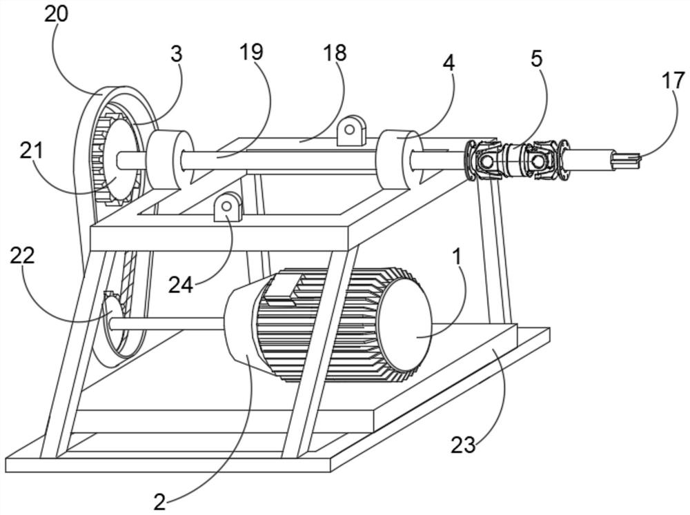
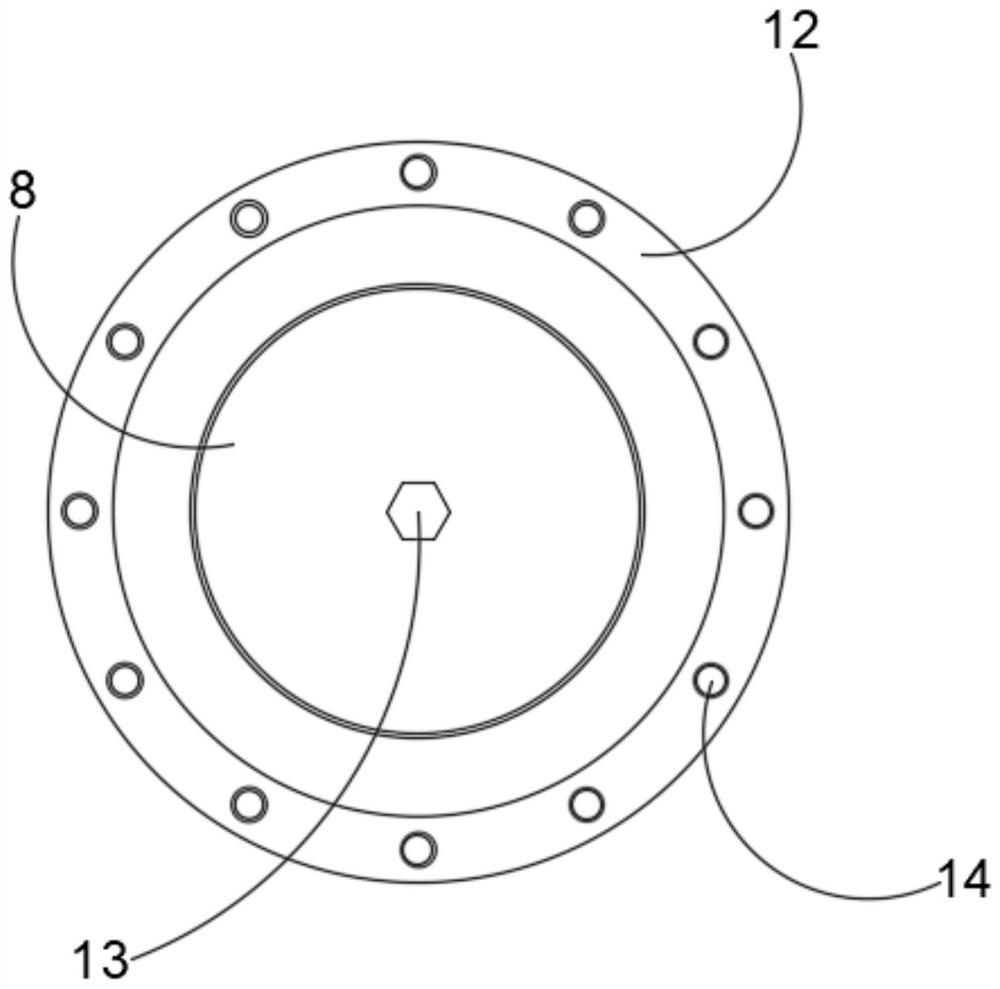
[0022] Embodiment one, by Figure 1-4 Given, the piston automatic piston compressor installation machine includes an assembly frame 18, a special extension sleeve 25 and a piston 8, and a motor 1 is installed on the assembly frame 18, and the motor 1 is connected with a driving sprocket 22 through a reducer 2. According to On-site maintenance efficiency and safety considerations, the transmission ratio of reducer 2 is 1:59 type cycloid reducer, the actual output speed is 25r / min, it only takes 3 minutes to connect the crosshead and piston rod in place, and the driving sprocket is 22 The driven sprocket 21 is connected through the transmission chain 3, and the driven sprocket 21 is fixedly connected with the transmission shaft 19. According to the on-site maintenance requirements of the propylene compressor, the motor with the explosion-proof mark ExdIIBT4Gb is selected, and the power of the motor 1 is determined according to the torque requirement. It is selected as 7.5kW, spr...

Embodiment 2

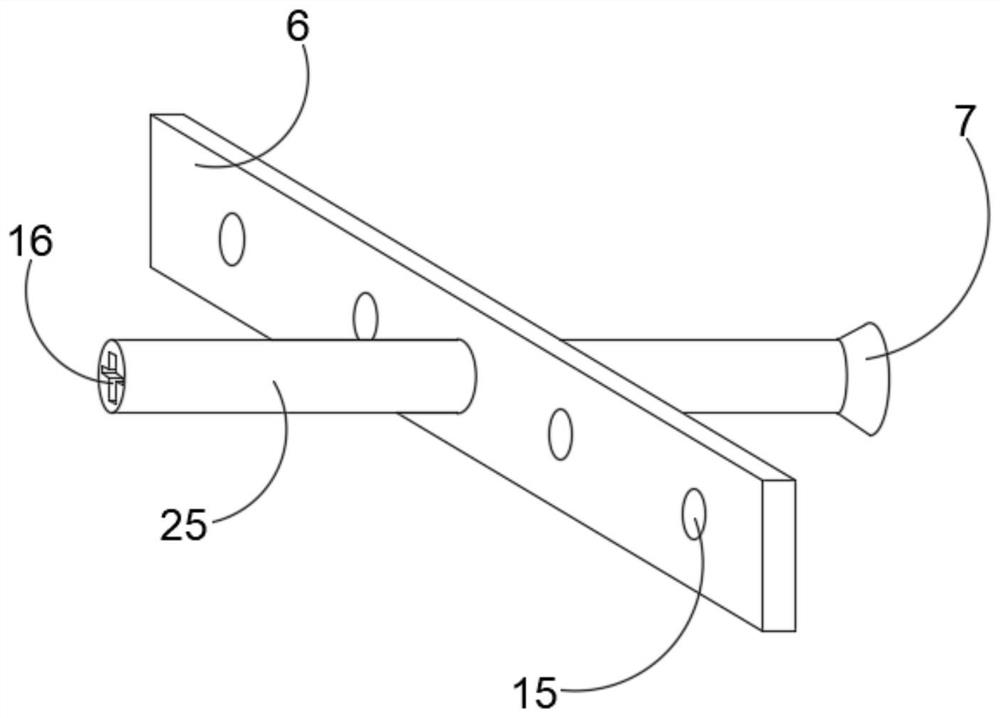
[0023] Embodiment 2, on the basis of Embodiment 1, the spline 17 is a cross-shaped structure, and the transmission joint groove 16 is a cross-shaped groove, the spline 17 can be in various shapes, and the cross-shaped spline 17 can be inserted into the transmission joint groove Drive lengthening special sleeve 25 to rotate and realize stable transmission in 16.

Embodiment 3

[0024] Embodiment 3, on the basis of Embodiment 1, a base 23 is fixedly welded on the assembly frame 18, the motor 1 is fixedly installed on the top of the base 23 through the motor base, and the motor 1 is mounted on the assembly frame 18 by using the base 23 The stable installation is conducive to ensuring the stability of the motor 1 when it is working.


PUM


Abstract

The invention discloses an automatic piston mounting machine for a piston type compressor, and relates to the technical field of reciprocating compressors, the automatic piston mounting machine comprises an assembly frame, a lengthened special sleeve and a piston, a motor is mounted on the assembly frame, the motor is in transmission connection with a driving chain wheel through a speed reducer, and the driving chain wheel is in transmission connection with a driven chain wheel through a transmission chain; a transmission shaft is fixedly connected to the driven chain wheel, a universal joint is installed on the transmission shaft, a spline is integrally connected to the end, away from the universal joint, of the transmission shaft, a transmission connecting groove used for being matched with the spline is formed in one end of the lengthened special sleeve, and a fixing support is fixed to the lengthened special sleeve. A plurality of through holes are formed in the fixing support in a penetrating mode. The problem that when an existing piston is installed, a loop bar needs to be installed at the piston end, manual rotation is time-consuming and labor-consuming is solved, the piston assembling efficiency can be improved, output of labor cost is reduced, and enterprise benefits are increased.

Description

technical field [0001] The invention relates to the technical field of reciprocating compressors, in particular to a piston automatic installation machine for piston compressors. Background technique [0002] In the reciprocating compressor currently produced, the piston rod of the piston is threadedly connected to the crosshead, and each time the piston is installed, a sleeve rod needs to be installed at the piston end to be manually rotated, which is time-consuming and laborious, and the manufacturer does not have any special tool to disassemble and install the piston. As we all know, the maintenance cycle of reciprocating piston compressors in chemical plants is relatively short, and efficient and safe special tools are needed to assist in completing the maintenance in a short period, so that the maintenance task can be completed without affecting production. [0003] For this reason, we propose a piston compressor piston automatic installation machine to solve the above ...

Claims


Application Information

Patent Timeline
Patent Type & Authority Applications(China)
IPC IPC(8): B23P19/04
CPCB23P19/04
Inventor 房民钟磊郭宗岩范宜波孙鹏山李鹏
Owner BEFAR GROUP CO LTD
Why Eureka
Try Eureka