
Binocular device

a binocular device and optical radiation technology, applied in medical science, surgery, diagnostics, etc., can solve the problem that not everything can be seen clearly in that way

Pending Publication Date: 2022-09-29
I MED TECH BV
View PDF0 Cites 0 Cited by
  • Summary
  • Abstract
  • Description
  • Claims
  • Application Information

AI Technical Summary

Benefits of technology

The camera's image sensor can pick up both infrared and visible light, which makes it easy to design a binocular device. However, this may affect the image quality because fewer visible light rays are available. The technical effect of this is that it allows for better image quality while still using a simple and light-weight design.

Problems solved by technology

However, not everything can be seen clearly in that way.

Method used


Image

  • Binocular device
  • Binocular device
  • Binocular device

Examples


Embodiment Construction

[0076]Certain exemplary embodiments will be described in greater detail, with reference to the accompanying drawings.

[0077]The matters disclosed in the description, such as detailed construction and elements, are provided to assist in a comprehensive understanding of the exemplary embodiments. Accordingly, it is apparent that the exemplary embodiments can be carried out without those specifically defined matters. Also, well-known operations or structures are not described in detail, since they would obscure the description with unnecessary detail.

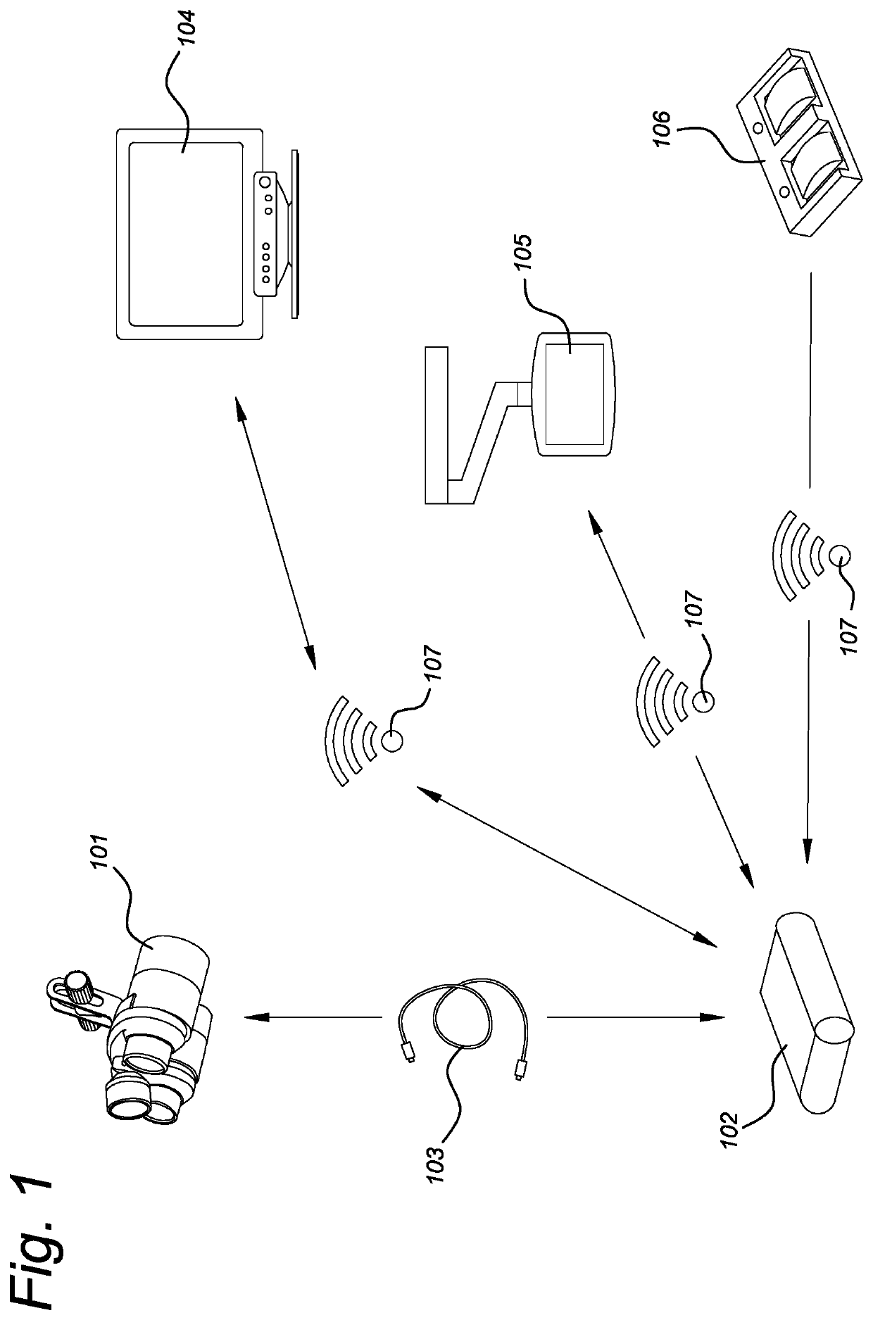
[0078]FIG. 1 shows an overview of an embodiment of a system for combining visual and infrared imaging. Although the system is explained here in the context of infrared imaging, a similar arrangement may be made for near-infrared or ultraviolet, or any other invisible wavelength band of radiation. The system comprises a head-mounted display 101 with a pair of built-in cameras. For example, the system is capable of magnification of the viewed...


PUM


Abstract

A binocular device for visualizing optical radiation comprises a support structure, a left camera, and a right camera coupled to the support structure. The left camera comprising left optics and a left image sensor, the right camera comprising right optics and a right image sensor, the left image sensor and the right image sensor being configured to create left and right video signals from detected optical radiation received from the corresponding left and right input optics about a same field of view along respective left and right input optical axes. A specular reflection is detected.

Description

FIELD OF THE INVENTION[0001]The invention relates to a binocular device for visualizing optical radiation. The invention further relates to a binocular device for visualizing visible and invisible radiation.BACKGROUND OF THE INVENTION[0002]When performing a surgical procedure, the surgeon uses bright lights in the operation room in order to be able to distinguish the tissues to be treated as good as possible. However, not everything can be seen clearly in that way. For example, certain tissue types, such as certain tumors, are not visible by the human eye. Those tissue types can sometimes be visualized by a technique of near-infrared imaging. This may be the case for tumor tissue.[0003]“Binocular Goggle Augmented Imaging and Navigation System provides real-time fluorescence image guidance for tumor resection and sentinel lymph node mapping”, by Suman B. Mondal et al., in Scientific Reports, vol. 5, no. 1, July 2015, discloses a system comprising a near-infrared (NIR) source comprisi...

Claims


Application Information

Patent Timeline
Patent Type & Authority Applications(United States)
IPC IPC(8): G02B21/20G02B21/00G02B27/01G02B27/28A61B90/00
CPCG02B21/20G02B21/0012G02B27/0172G02B27/288A61B90/361G02B2027/0134A61B2090/502G02B2027/014G02B25/004G02B25/02A61B2090/3616A61B2090/365A61B2090/371A61B90/30A61B2017/00973A61B2017/00119A61B2017/00203A61B2017/00207A61B90/35A61B2090/373H04N13/239H04N13/344H04N2213/001H04N13/296H04N13/254G02B23/18G02B2027/0178
Inventor GRAHAM, VINCENTWIERINGA, FOKKO PIETER
Owner I MED TECH BV
Learn More