
Meter apparatus for measuring parameters of electrical quantity

a technology of electrical quantity and meter, which is applied in the direction of resistance/reactance/impedence, voltage-current phase angle, instruments, etc., can solve the problems of inability to meet the requirements of the prior-arts, high cost, and inability to use, and achieve simple circuit implementation, high accuracy, and low cost

Active Publication Date: 2022-03-22
TELECOM ITALIA SPA
View PDF4 Cites 0 Cited by
  • Summary
  • Abstract
  • Description
  • Claims
  • Application Information

AI Technical Summary

Benefits of technology

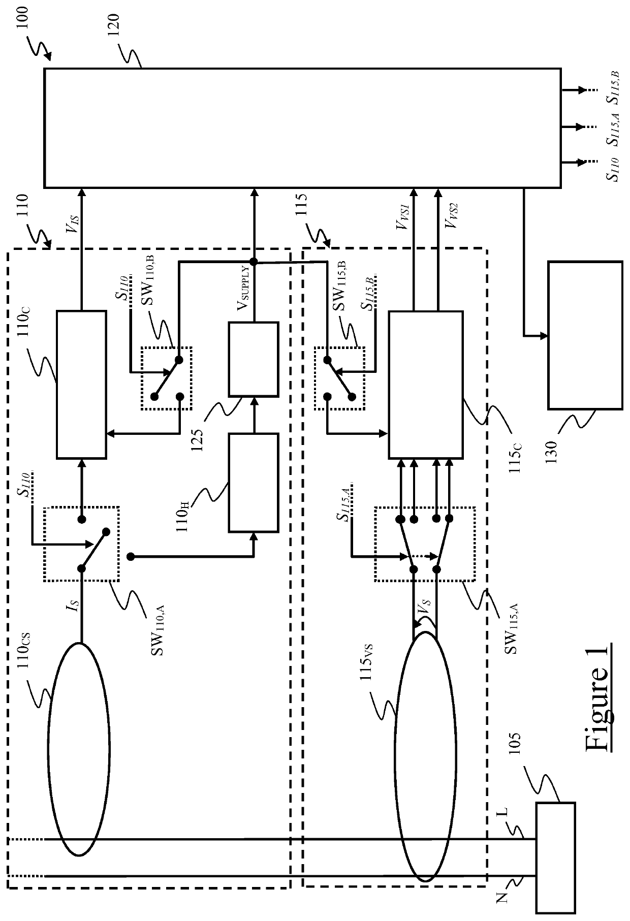
[0039]The present invention allows determining electric voltage and / or electric current waveforms (i.e., amplitude and phase shift) of an AC signal (for example, the AC signal in the line and neutral wires of an electrical distribution system) by using inductive and capacitive couplings. Thanks to inductive and capacitive couplings, the electric voltage and / or electric current waveforms are determined in a non-intrusive manner (i.e., without altering the overall load of the electrical distribution system) and independently from wire geometry (which may also significantly differ from a measure point to another one) and from wire spatial geometry or arrangement (i.e., regardless of whether the wire is bent or twisted), thus providing highly precise measurements.
[0040]Moreover, the proposed meter apparatus features a simple circuit implementation requiring low cost hardware, so that it can profitably be implemented based on the multi-sensor approach.

Problems solved by technology

The Applicant has recognized that none of the cited prior-arts solutions is satisfactory.
The Applicant has found that current meter apparatuses based on multi-sensor approach achieve a consumption breakdown, but need a large number of sensors in the residential environment.
This leads to high costs, and discourages their use.
According to the Applicant, in “Self-powered smart meter with synchronized data” paper, each meter apparatus is arranged for collecting current, voltage and associated phase angles in an intrusive manner, which makes measurements not fully reliable.

Method used


Image

  • Meter apparatus for measuring parameters of electrical quantity
  • Meter apparatus for measuring parameters of electrical quantity
  • Meter apparatus for measuring parameters of electrical quantity

Examples


second embodiment

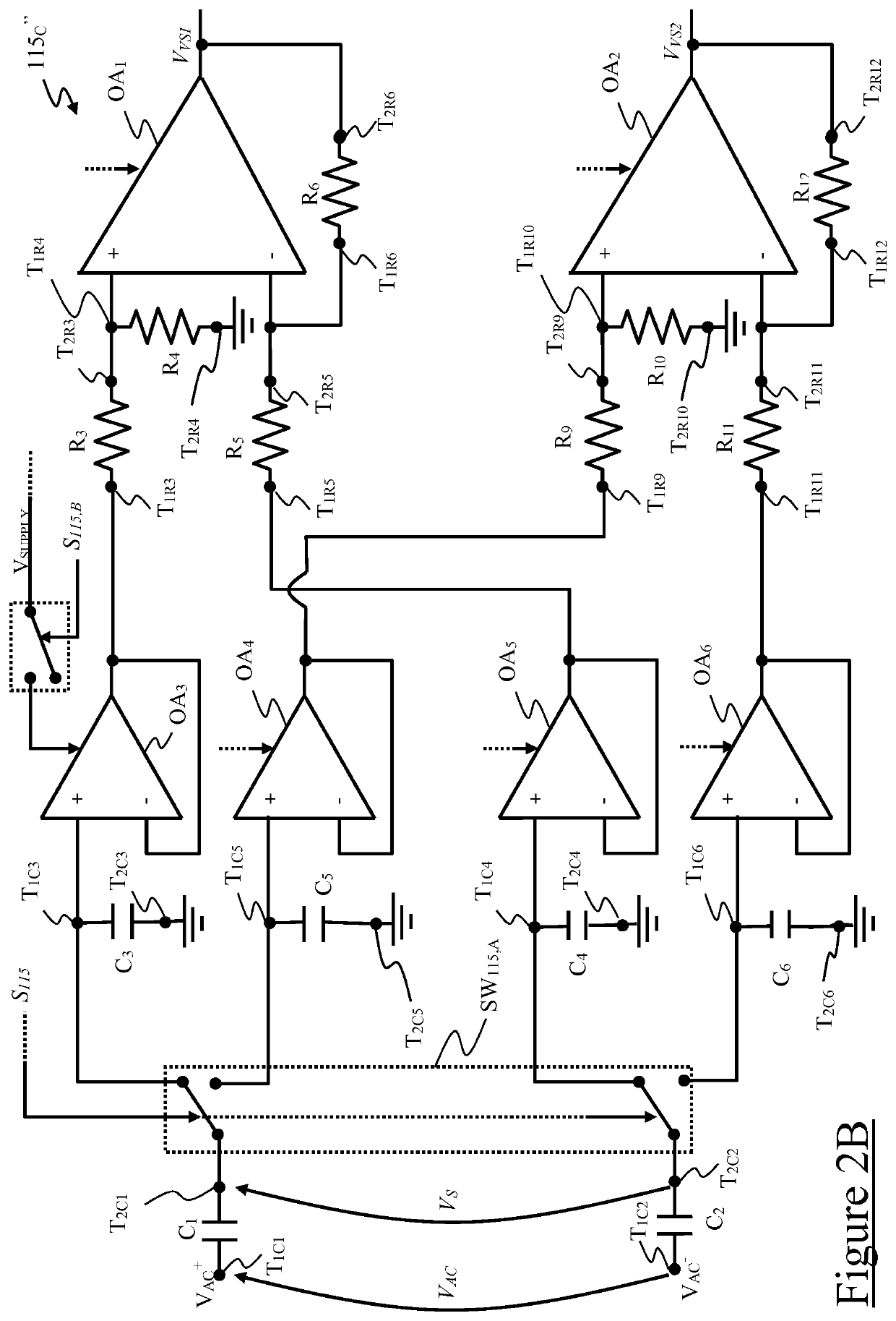
[0141]With reference now to FIG. 2B, a circuit representation of a conditioning module 115C″ according to the present invention is shown.

[0142]The conditioning module 115C″ is almost entirely similar to the conditioning module 115C′, for which reason same elements will not be discussed again.

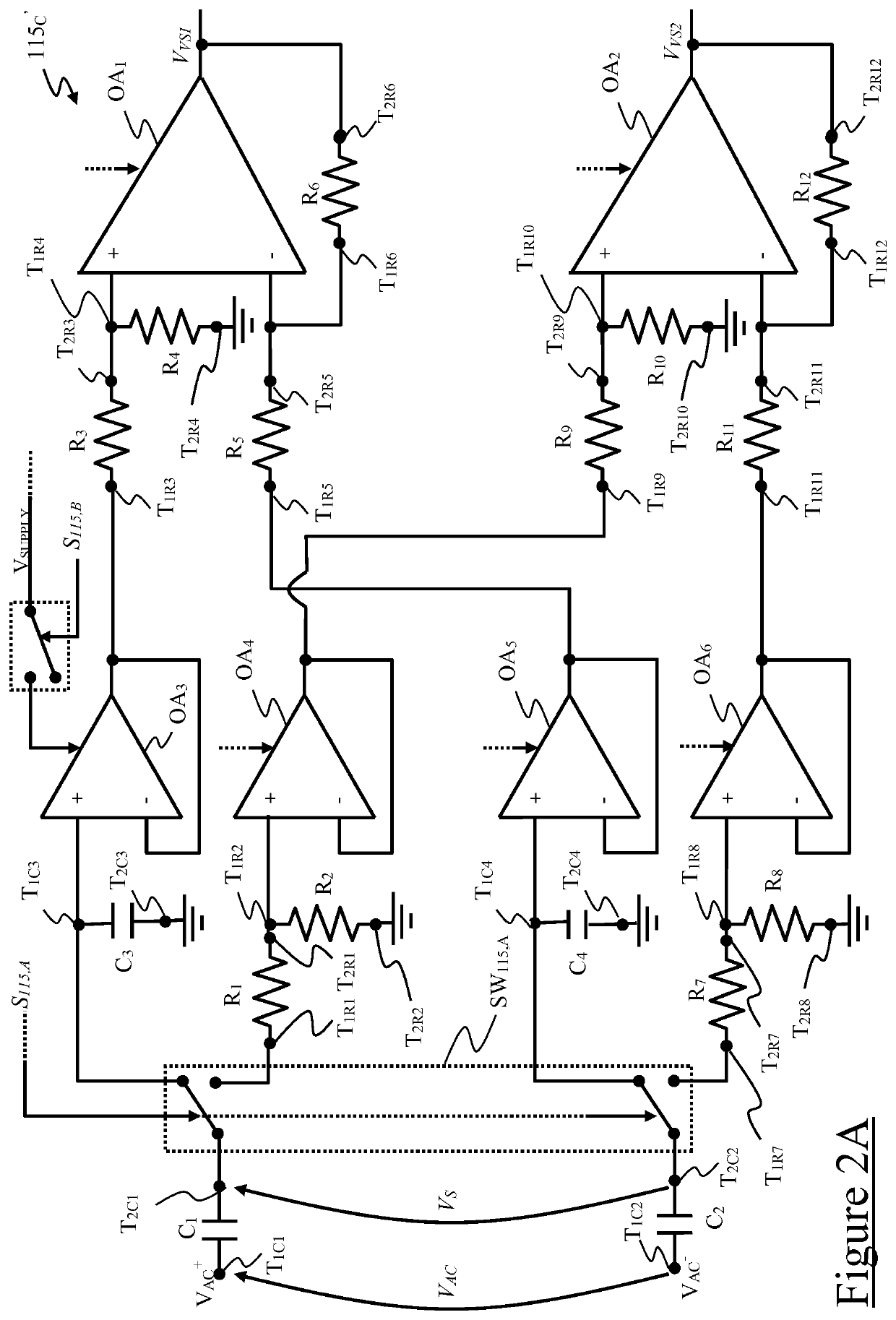
[0143]The conditioning module 115C″ differs from the conditioning module 115C′ in that the first and second input stages comprise, instead of the high-pass filter (defined by the first C1 and second C2 sensing capacitors and, respectively, the first R1,R2 and second R7,R8 input resistors, as discussed above), an impedance voltage divider for the AC voltage VAC. In the example at issue wherein the voltage measurement section 115 is configured for providing the first VVS1 and / or second VVS2 voltage measure signals based on capacitive coupling with line L and neutral N wires, the impedance voltage divider is advantageously a capacitive voltage divider.

[0144]In the exemplary illustrated embodiment, ...

third embodiment

[0161]With reference now to FIG. 2C, it shows a circuit representation of a conditioning module 115C′″ according to the present invention.

[0162]The conditioning module 115C′″ is almost entirely similar to the conditioning module 115C′, for which reason same elements will not be discussed again.

[0163]The conditioning module 115C′″ differs from the conditioning module 115C′ in that it comprises, instead of the high-pass filter (which, in the conditioning module 115C′, is defined by the first C1 and second C2 sensing capacitors and, respectively, the first R1,R2 and second R7,R8 input resistors, as discussed above), a differentiator arrangement for the AC voltage VAC.

[0164]In the exemplary illustrated embodiment, the first and second input stages comprise first R13 and second R14 input resistors electrically coupleable to the first C1 and second C2 sensing capacitors, respectively, and first OA7 and second OA8 operational amplifiers electrically coupled to the first R13 and second R14 ...

first embodiment

[0186]Moreover, with respect to the first embodiment, the conditioning module 115C′″ allows avoiding the determination of the phase shift between the first VVS1 and second VVS2 voltage measure signals, which could be a relevant source of error in some applications. In particular, this approach significantly improves the amplitude measurement with an error lower than 5%.

[0187]In addition, with respect to the conditioning module 115C″, wherein the ADC module should exhibit a very high sensitivity (i.e., a resolution of the order of μV) thus determining relatively high complexity and costs, the conditioning module 115C′″ allows achieving very low costs and reliability.


PUM


Abstract

A meter apparatus is provided for determining parameters of an AC electric signal in first and second wires, the AC signal including an AC electric current and an AC electric voltage, the apparatus including a measurement section to provide first and second measure signals each one indicative of the AC voltage based on a first capacitive coupling with the first wire and on a second capacitive coupling with the second wire, the first and second measure signals depending on capacitance values of the first and second capacitive couplings, and a control unit to determine said capacitance values of the first and second capacitive couplings according to the first and second measure signals, and determining the amplitude of the AC voltage according to the first or second measure signal, and to the capacitance values of the first and second capacitive couplings.

Description

BACKGROUND OF THE INVENTIONField of the Invention[0001]The present invention generally relates to a meter apparatus for measuring parameters (e.g., amplitude and / or phase shift) of electrical quantities (e.g., electric voltage and / or electric current). In particular, the present invention relates to a meter apparatus for effectively measuring parameters of electrical quantities of any wire in operation without the use of batteries and in a non-intrusive manner.Overview of the Related Art[0002]In modern society, electric power is critical to daily life. Therefore, measurement of parameters (such as amplitude and / or phase shift) of electrical quantities (such as electric voltage and / or electric current) in wires (such as in line and / or neutral wires) in operation is of the utmost importance for achieving efficient control on power usage of electric loads in residential households and buildings.[0003]For example, determining the amplitude of the electric voltage and of the electric cur...

Claims


Application Information

Patent Timeline
Patent Type & Authority Patents(United States)
IPC IPC(8): G01R15/12G01R15/16G01R15/18G01R27/26
CPCG01R15/12G01R15/16G01R15/18G01R27/2605G01R21/006G01R25/00
Inventor BALSAMO, DOMENICOBELLA, VALTERBELLIFEMINE, FABIO LUIGIBENINI, LUCABRUNELLI, DAVIDEVILLANI, CLEMENTE
Owner TELECOM ITALIA SPA
Learn More