
Battery box

a battery box and box body technology, applied in the field of battery boxes, can solve the problems of poor bonding effect and insulation strength, and achieve the effect of ensuring bonding strength and ensuring the safety performance of the battery box

Active Publication Date: 2022-03-22
CONTEMPORARY AMPEREX TECH CO
View PDF6 Cites 0 Cited by
  • Summary
  • Abstract
  • Description
  • Claims
  • Application Information

AI Technical Summary

Benefits of technology

[0005]In view of the problem existing in the background, an object of the present disclosure is to provide a battery box and a vehicle, the battery box ensures the bonding strength of the battery box, meanwhile improves the insulation performance of the battery box, in turn effectively ensures the safety performance of the battery box.
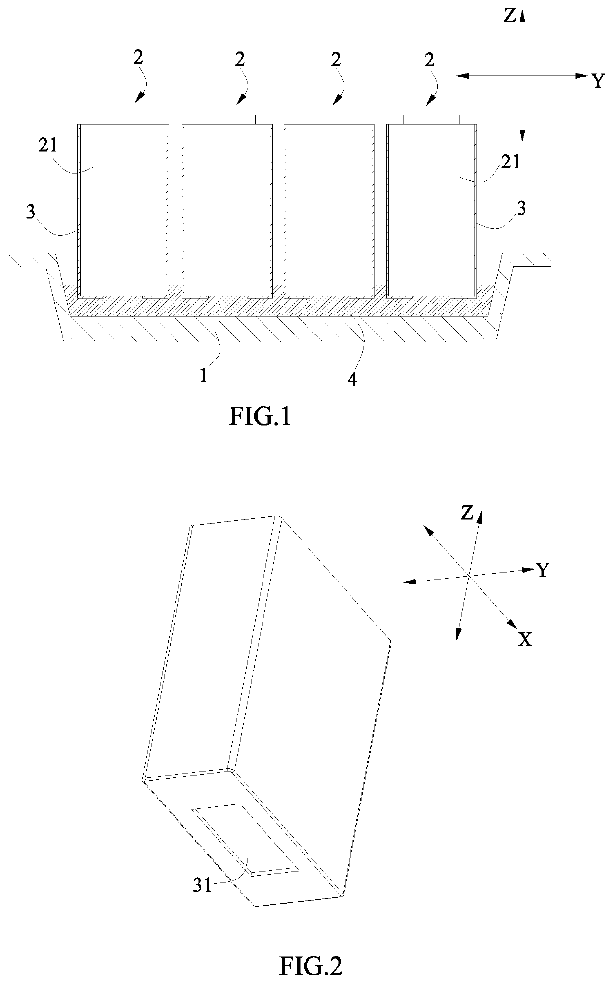
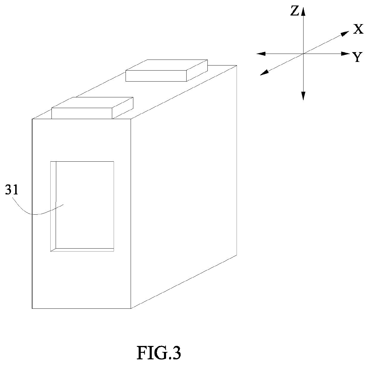
[0019]The present disclosure has the following beneficial effects: because the insulating film is provided with the opening, a portion of the adhesive bonds the case of the battery to the box body at the opening, a portion of the adhesive bonds the insulating film to the box body at the outside of the opening, it ensures the bonding strength between the battery and the box body. Meanwhile, because A, L1, ρ1, L2, ρ2 and the area A1 of the opening of the insulating film meet the above relationship, it makes a covering area of the insulating film on the battery meet the requirement of the insulating strength (that is, the insulation failure of the inside of the battery box does not occur), thereby ensuring the safety performance of the battery box.

Problems solved by technology

Because the insulating film is usually made of a high polymer material such as PET, PC etc., and the surface energy of these high polymer materials are relatively lower, when the lower box body is bonded to the insulating film outside of the case of the battery by the adhesive, the bonding effect is not good.
Although this arrangement ensures the bonding strength of the battery box, the safety problem due to the insufficient insulation strength of the battery box often occurs in the long-term use of the battery box.

Method used


Image

  • Battery box
  • Battery box
  • Battery box

Examples


Embodiment Construction

[0033]To make the object, technical solutions, and advantages of the present disclosure more apparent, hereinafter the present disclosure will be further described in detail in combination with the accompanying figures and the embodiments. It should be understood that the specific embodiments described herein are merely used to explain the present disclosure but are not intended to limit the present disclosure.

[0034]In the description of the present disclosure, unless otherwise specifically defined and limited, the term “plurality” is two or more. For the persons skilled in the art, the specific meanings of the abovementioned terms in the present disclosure can be understood according to the specific situation.

[0035]In the description of the present disclosure, it should be understood that spatially relative terms, such as “above”, “below” and the like, are described based on orientations illustrated in the figures, but are not intended to limit the embodiments of the present disclo...


PUM

PropertyMeasurementUnit
volume resistivityaaaaaaaaaa

Abstract

The present disclosure provides a battery box, the battery box comprises a box body, batteries, an insulating film and a adhesive. Each battery comprises a case. The insulating film covers the case of each battery and is provided with an opening. The adhesive is provided between the battery and the box body. The A1, A, L1, ρ1, L2 and ρ2 meet a following relationship:L1A1·ρ1·L2A-A1·ρ2L1A1·ρ1+L2A-A1·ρ2≥10⁢⁢M⁢⁢Ω.Because the insulating film is provided with the opening, a portion of the adhesive bonds the case to the box body at the opening, a portion of the adhesive bonds the insulating film to the box body at the outside of the opening, it ensures the bonding strength between the battery and the box body. Meanwhile, it makes a covering area of the insulating film on the battery meet the requirement of the insulating strength, thereby ensuring the safety performance.

Description

CROSS-REFERENCE TO RELATED APPLICATIONS[0001]The present application claims priority to Chinese patent application No. CN201811630123.8, filed on Dec. 29, 2018, which is incorporated herein by reference in its entirety.FIELD OF THE PRESENT DISCLOSURE[0002]The present disclosure relates to the field of battery technology, and particularly relates to a battery box and a vehicle.BACKGROUND OF THE PRESENT DISCLOSURE[0003]At present, in many battery boxes, the bottom of the battery is directly fixed on the lower box body of the battery box by the manner of bonding. Because the lower box body and the case of the battery are usually made of metal (such as aluminum), and in order to insulate the case of the battery, an insulating film generally covers the case.[0004]Because the insulating film is usually made of a high polymer material such as PET, PC etc., and the surface energy of these high polymer materials are relatively lower, when the lower box body is bonded to the insulating film o...

Claims


Application Information

Patent Timeline
Patent Type & Authority Patents(United States)
IPC IPC(8): H01M50/20B60R16/04H01M50/119H01M50/121H01M50/124H01M50/131H01M50/133H01M50/209
CPCH01M50/20B60R16/04H01M2220/20H01M50/131H01M50/119H01M50/209H01M50/121H01M50/133H01M50/124B60L50/64Y02T10/70Y02E60/10
Inventor CHEN, TIANMINGCHEN, ZHIMING
Owner CONTEMPORARY AMPEREX TECH CO
Learn More