Clad material and electronic device housing

a technology of electronic devices and cladding, which is applied in the direction of manufacturing tools, transportation and packaging, and solventing apparatus, can solve the problems of low corrosion resistance of mg base alloy and the likelihood of layer separation from each other, and achieve the effect of suppressing an increase in its specific gravity and ensuring bonding strength

Active Publication Date: 2020-01-14
HITACHI METALS LTD
View PDF11 Cites 0 Cited by
  • Summary
  • Abstract
  • Description
  • Claims
  • Application Information

AI Technical Summary

Benefits of technology

[0020]According to the present invention, as hereinabove described, the clad material capable of sufficiently ensuring the bonding strength on its bonding interface while suppressing an increase in its specific gravity and the electronic device housing using the clad material can be provided.

Problems solved by technology

However, there is such a disadvantage that the Mg base alloy is low in corrosion resistance.
However, when the clad material is prepared by directly bonding the layer made of the Mg base alloy and the layer made of the Al base alloy to each other, a fragile intermetallic compound is deposited on a bonding interface between the layers, and hence there is such a disadvantage that the layers are likely to be separated from each other.

Method used


Image

  • Clad material and electronic device housing
  • Clad material and electronic device housing
  • Clad material and electronic device housing

Examples


first embodiment

[0042]

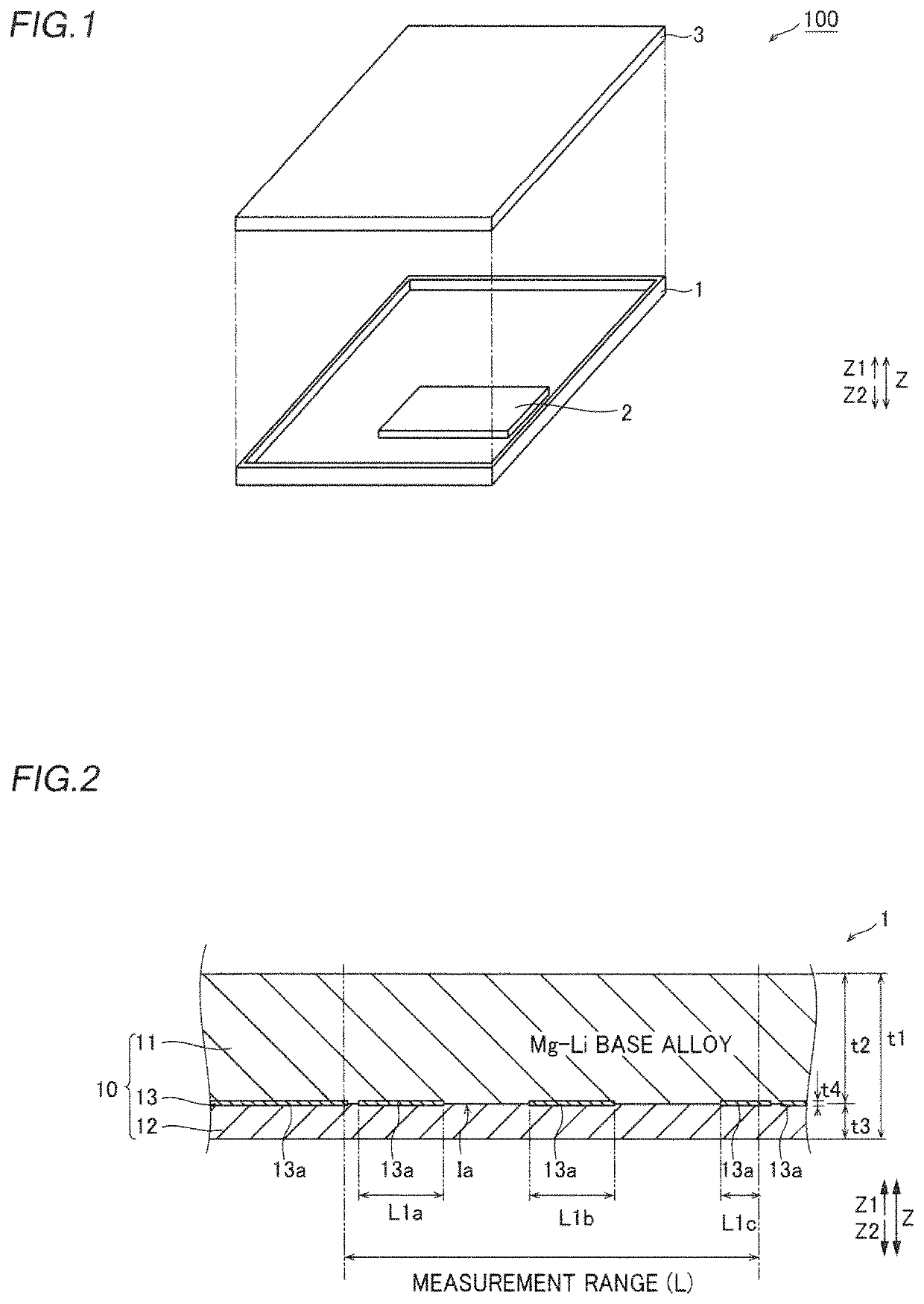
[0043]The structure of an electronic device 100 according to a first embodiment of the present invention is now described with reference to FIGS. 1 and 2.

[0044]The electronic device 100 according to the first embodiment of the present invention is a portable electronic device, for example. This electronic device 100 includes a box-shaped housing 1 used as a structural member of the electronic device 100, a substrate 2 arranged on the housing 1, and a display 3 that is connected to the substrate 2 and displays an image etc. The housing 1 is an example of an “electronic device housing” in the claims.

[0045](Structure of Clad Material)

[0046]The housing 1 is made of a clad material 10, as shown in FIG. 2. Specifically, the housing 1 is made of the clad material 10 including a Mg—Li layer 11, an Al layer 12, and a bonding portion 13. In the clad material 10, the Mg—Li layer 11 and the Al layer 12 are bonded to each other in a state where the same are stacked in this order from a Z1 ...

second embodiment

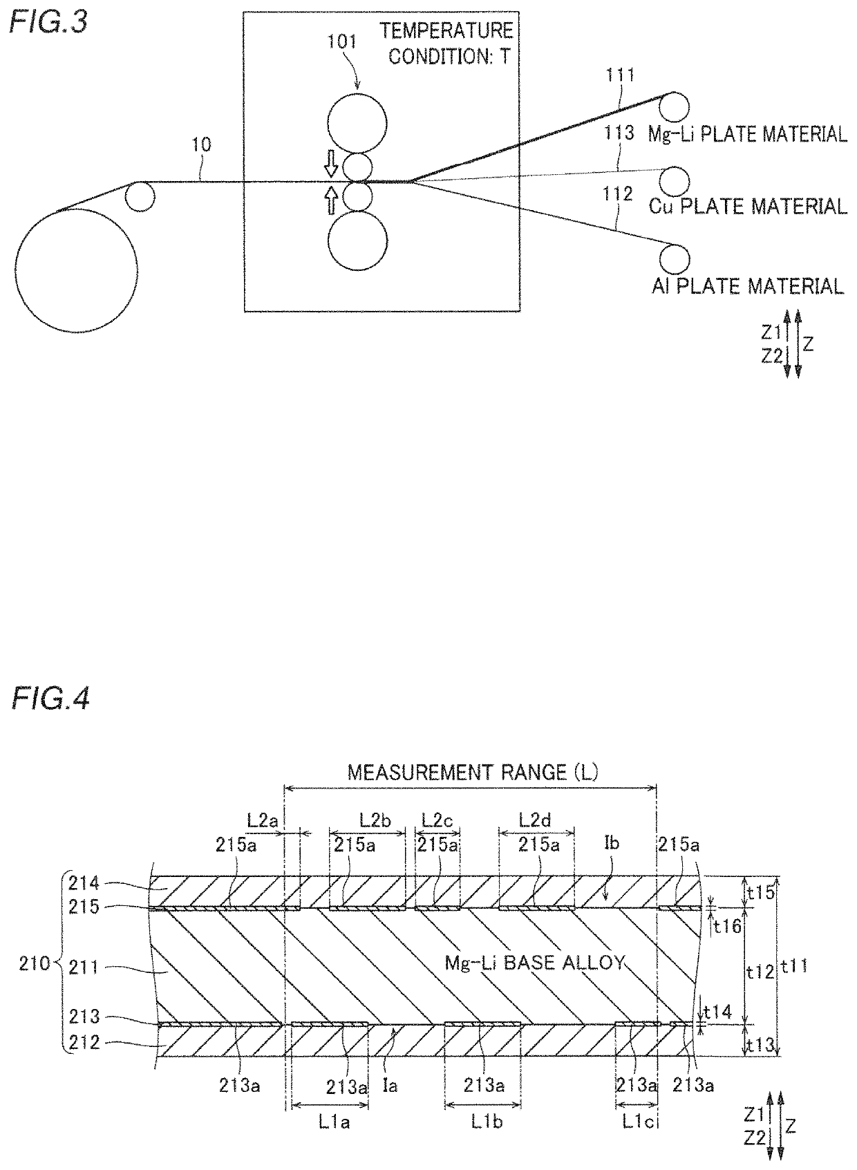
[0074]A second embodiment of the present invention is now described with reference to FIG. 4. In the second embodiment, the case where a clad material 210 has a five-layered structure is described.

[0075]

[0076]According to the second embodiment, the clad material 210 includes an Al layer 214 and a bonding portion 215 in addition to a Mg—Li layer 211, an Al layer 212, and a bonding portion 213. In the clad material 210, the Al layer 214, the Mg—Li layer 211, and the Al layer 212 are bonded to each other in a state where the same are stacked in this order from a Z1 side to a Z2 side. Furthermore, the bonding portion 213 is arranged on a bonding interface Ia between the Mg—Li layer 211 and the Al layer 212 on the Z2 side in a section view when the clad material 210 is cut in a thickness direction (direction Z). In addition, the bonding portion 215 is arranged on a bonding interface Ib between the Mg—Li layer 211 and the Al layer 214 on the Z1 side in the section view. The Mg—Li layer 21...

examples

[0096]An experiment and a simulation conducted in order to confirm the effect of the present invention are now described with reference to FIGS. 3 to 20. As the experiment, measurement of the abundance of the bonding portion and measurement of the peel strength were performed. As the simulation, the specific gravity of the clad material with respect to the thickness percentage of the Mg—Li layer in the case where the thickness of the clad material and the thickness of the bonding portion were set to predetermined values was obtained.

[0097]

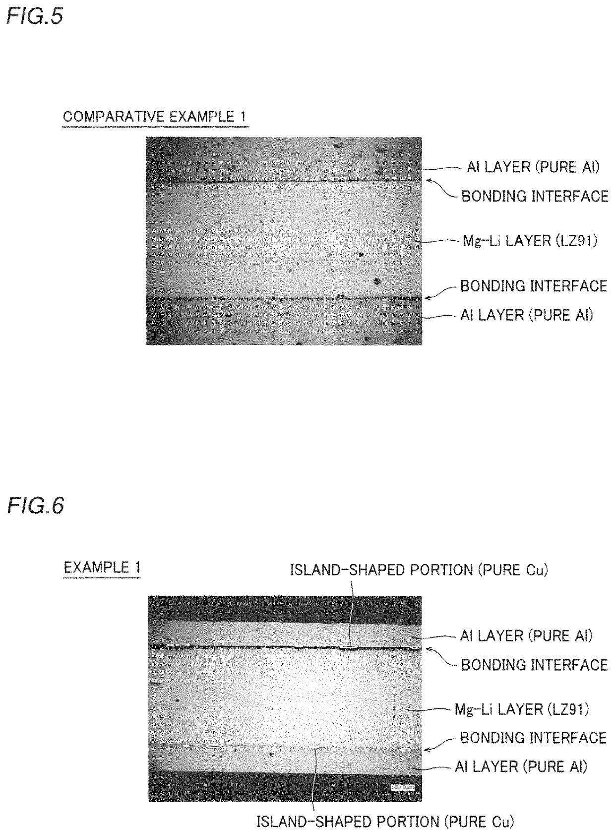
[0098]First, the clad material 210 according to Example 1 that corresponds to the aforementioned second embodiment was prepared. Specifically, first, a Mg—Li plate material made of LZ91 (Mg—Li—Zn alloy), a pair of Al plate materials made of A1080 (pure Al), and a pair of Cu plate materials made of C1020 (pure Cu) were prepared. The specific gravity of LZ91 is 1.50, the specific gravity of A1080 is 2.70, and the specific gravity of C1020 is 8.94.

[00...


PUM


Abstract

This clad material includes a first layer made of a Mg—Li base alloy, a second layer made of an Al base alloy, and a first bonding portion arranged on a bonding interface between the first layer and the second layer in a section view when cut in a thickness direction and made of a Cu base alloy. The clad material has a specific gravity of 2.10 or less.

Description

TECHNICAL FIELD[0001]The present invention relates to a clad material and an electronic device housing made of the clad material.BACKGROUND ART[0002]A Mg (magnesium) base alloy is currently known as a lightweight material used for a housing or the like of a portable terminal. However, there is such a disadvantage that the Mg base alloy is low in corrosion resistance. Thus, it is studied that a clad material in which a layer made of the Mg base alloy and a layer made of an Al (aluminum) base alloy are bonded to each other is prepared such that a material in which an Al base alloy enables improvement in corrosion resistance while a Mg base alloy enables weight saving is obtained.[0003]However, when the clad material is prepared by directly bonding the layer made of the Mg base alloy and the layer made of the Al base alloy to each other, a fragile intermetallic compound is deposited on a bonding interface between the layers, and hence there is such a disadvantage that the layers are li...

Claims


Application Information

Patent Timeline
Patent Type & Authority Patents(United States)
IPC IPC(8): B32B15/01B23K35/30H05K5/04B23K20/04B23K103/08B23K103/10
CPCH05K5/04B32B15/017B23K20/04B23K35/302B23K2103/15B23K2103/10Y10T428/12347C22C23/00C22F1/04C22F1/06B23K2103/12B23K2103/18B32B15/20B32B2457/00B32B15/01
Inventor YAMAMOTO, SHINJIINOUE, RYOJI
Owner HITACHI METALS LTD
Why Eureka
Try Eureka