Sputtering Target Having Alarm Function

Inactive Publication Date: 2013-08-15
SOLAR APPLIED MATERIALS TECHNOLOGY CORPORATION
View PDF3 Cites 0 Cited by
  • Summary
  • Abstract
  • Description
  • Claims
  • Application Information

AI Technical Summary

Benefits of technology

The present invention provides a sputtering target with an alarm function that can maintain the bonding strength of the target body to the backing body and prevent damage to the backing body during the sputtering process. The alarm body can detect a gas component and stop the sputtering process to prevent damage to the backing body. The at least one alarm body is preferably embedded in the target body and is projected onto the bonding plane, maximizing the usable erosion depth of the target body and improving the production efficiency of the sputtering process. The length of each alarm body and the percentage of the area of each alarm body projected onto the bonding plane are controlled to ensure the bonding strength and heat-removing efficiency of the sputtering target.

Problems solved by technology

However, if the sum of area(s) of the at least one alarm body projected onto the bonding plane is too large, the target body cannot have enough bonding strength to bond with the backing body, and thereby the sputtering quality of the sputtering target will be reduced.
In addition, if the percentage of the area of each single alarm body projected onto the bonding plane relative to the area of the bonding plane is more than 1%, the local heat-removing efficiency of the backing body of the sputtering target will be reduced, and furthermore the property of film will be deteriorated.

Method used


Image

  • Sputtering Target Having Alarm Function
  • Sputtering Target Having Alarm Function
  • Sputtering Target Having Alarm Function

Examples


embodiment 1

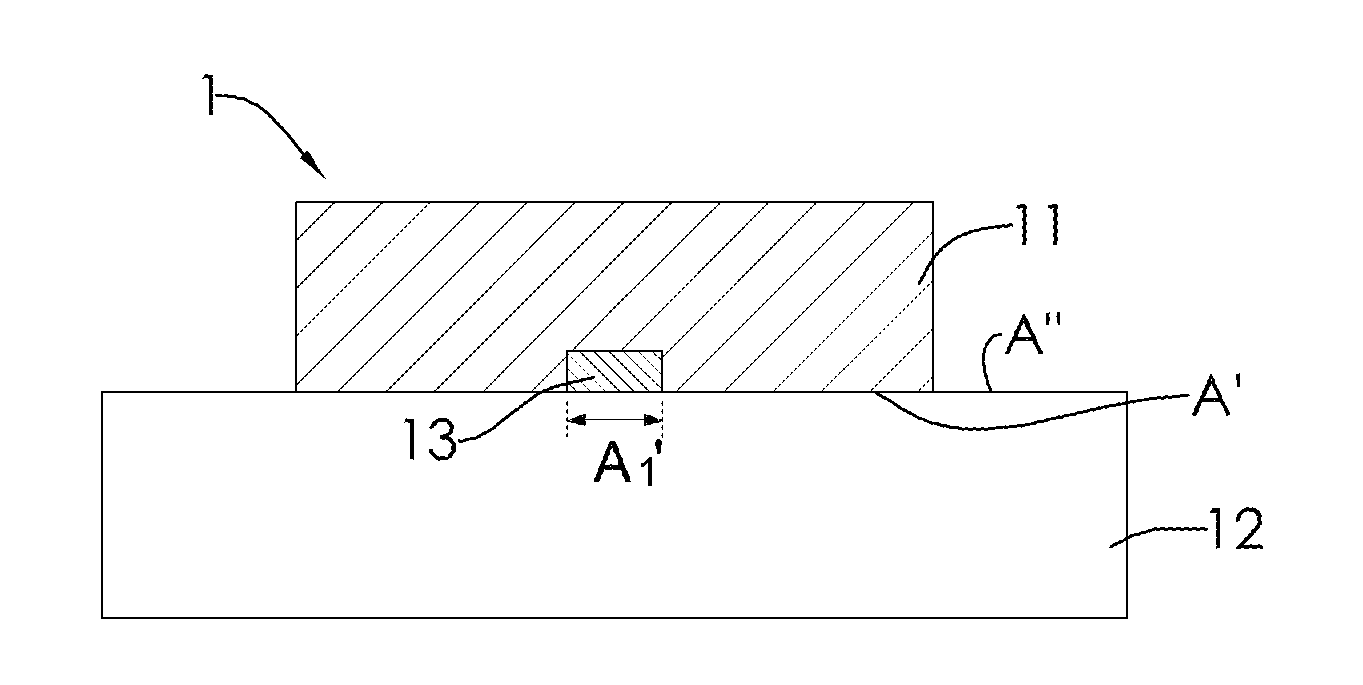
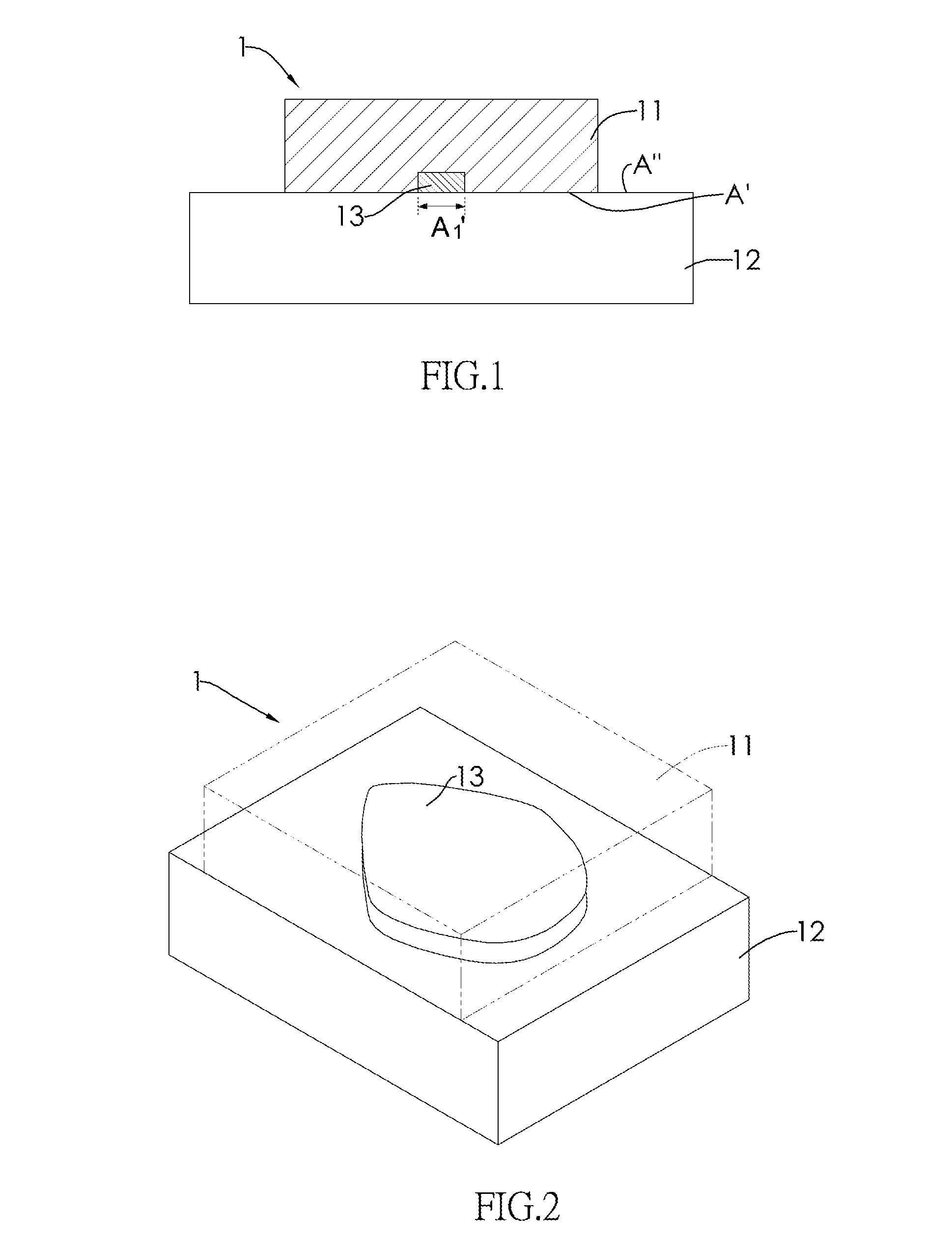
[0030]With reference to FIG. 1 and FIG. 2, the sputtering target having alarm function 1 of the present invention comprises: a target body 11 including a target material and having a bonding plane A′; a backing body 12 bonded with the bonding plane A′ of the target body 11; and an alarm body 13 is filled with the distinguishable material and coated onto the bonding plane A′ of the target body 11.

[0031]In Embodiment 1, a percentage of an area of the alarm body 13 projected onto the bonding plane A1′ relative to an area of the bonding plane A′ is less than or equal to 20%. As shown by the present embodiment, the area of the alarm body 13 projected onto the bonding plane A′ is equal to the area of the alarm body 13 in contact with the top face A″ of the backing body 12. If the projection area A1′ of the alarm body 13 is controlled within a suitable range, the bonding strength of the target body 11 to the backing body 12 and the heat-removing efficiency of the backing body 12 can be mai...

embodiment 2

[0036]With reference to FIGS. 4 and 5, the sputtering target having alarm function 2 in accordance with the present invention comprises multiple alarm bodies 23.

[0037]As described by the Embodiment 1, the sputtering target having alarm function 2 of the present embodiment comprises: a backing body 22, and a target body 21 disposed on the backing body 22. Wherein, the target body 21 has a bonding plane A′, and the backing body 22 is bonded with the bonding plane A′ of the target body 21.

[0038]The difference between Embodiments 1 and 2 is that the sputtering target 2 of the present embodiment comprises multiple alarm bodies 23, and the multiple alarm bodies 23 are disposed at where the erosion profile of the target body 21 is projected onto the bonding plane A′. With reference to FIG. 5, the predetermined erosion profile 24 of the target body 21 sputtered by using a sputtering equipment is mapped on the target body 21 in advance. Each of the multiple alarm bodies 23 will be disposed a...


PUM

PropertyMeasurementUnit
Fractionaaaaaaaaaa
Fractionaaaaaaaaaa
Lengthaaaaaaaaaa

Abstract

The present invention provides a sputtering target having alarm function. The sputtering target comprises: a target body including a target material and having a bonding plane; a backing body bonded with the bonding plane of the target body; and at least one alarm body embedded in the target body. Wherein, a length of each alarm body, ratios of an area of each alarm body and the sum of area(s) of the at least one alarm body projected onto the bonding plane relative to an area of the bonding plane are controlled in a suitable range. Thus, the bonding strength and the heat-removing efficiency of the sputtering target can be maintained, and the distinguishable material of the alarm body can evolve a gas component distinguishable from a sputtering environment serving as an alarm signal for stopping the sputtering process in time.

Description

BACKGROUND OF THE INVENTION[0001]1. Field of the Invention[0002]The present invention relates to a sputtering target having alarm function, and particularly to a sputtering target comprising alarm bodies for producing alarm signals for stopping sputtering process.[0003]2. Description of the Prior Arts[0004]Physical vapor deposition, PVD, is a conventional coating method for forming films, wherein atoms or molecules are physically deposited onto a substrate such as metal substrate, alloy substrate, ceramic substrate, and silicon wafer substrate, etc, and then a film is formed on the substrate.[0005]Physical vapor deposition is classified into evaporation deposition and sputtering deposition. With the glow discharge effect, the inert gas is ionized and then bombards the surface of target, and the atoms or molecules of targets will be struck out and then deposited onto the substrate, and finally form a uniform film. Hence, physical vapor deposition becomes the most common film-forming ...

Claims


Application Information

Patent Timeline
IPC IPC(8): C23C14/54C23C14/34
CPCC23C14/3407C23C14/54
Inventor HU, SHU-HUALU, MING-CHANGSU, PAI-YINGCHEN, JUNG-SHENGYIN, HSIN-CHUN
Owner SOLAR APPLIED MATERIALS TECHNOLOGY CORPORATION
Why Eureka
Try Eureka