Method for surgical application of a glenoid prosthesis component of a shoulder joint prosthesis and relating surgical instruments

a technology of glenoid prosthesis and shoulder joint, which is applied in the field of glenoid prosthesis component surgical application and relating surgical instruments, can solve the problems of compromising the function of said important muscle, surgeons cannot visualize the contact surfaces the humeral head top, and the surgical technique described above has a major drawback relating to the invasiveness of the glenoid cavity exposur

Active Publication Date: 2022-04-12
LIMA CORPORATE SPA
View PDF7 Cites 0 Cited by
  • Summary
  • Abstract
  • Description
  • Claims
  • Application Information

AI Technical Summary

Benefits of technology

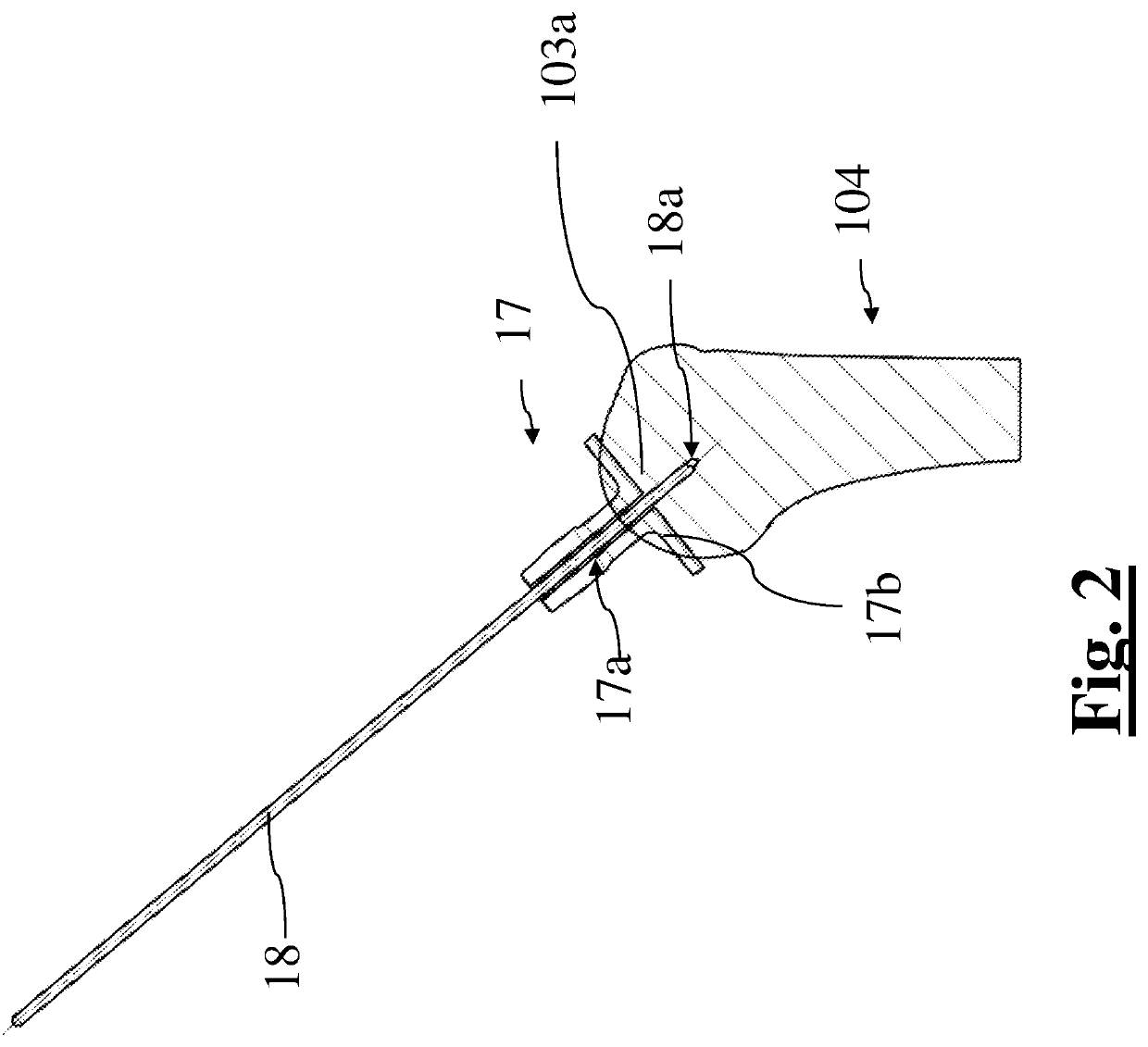
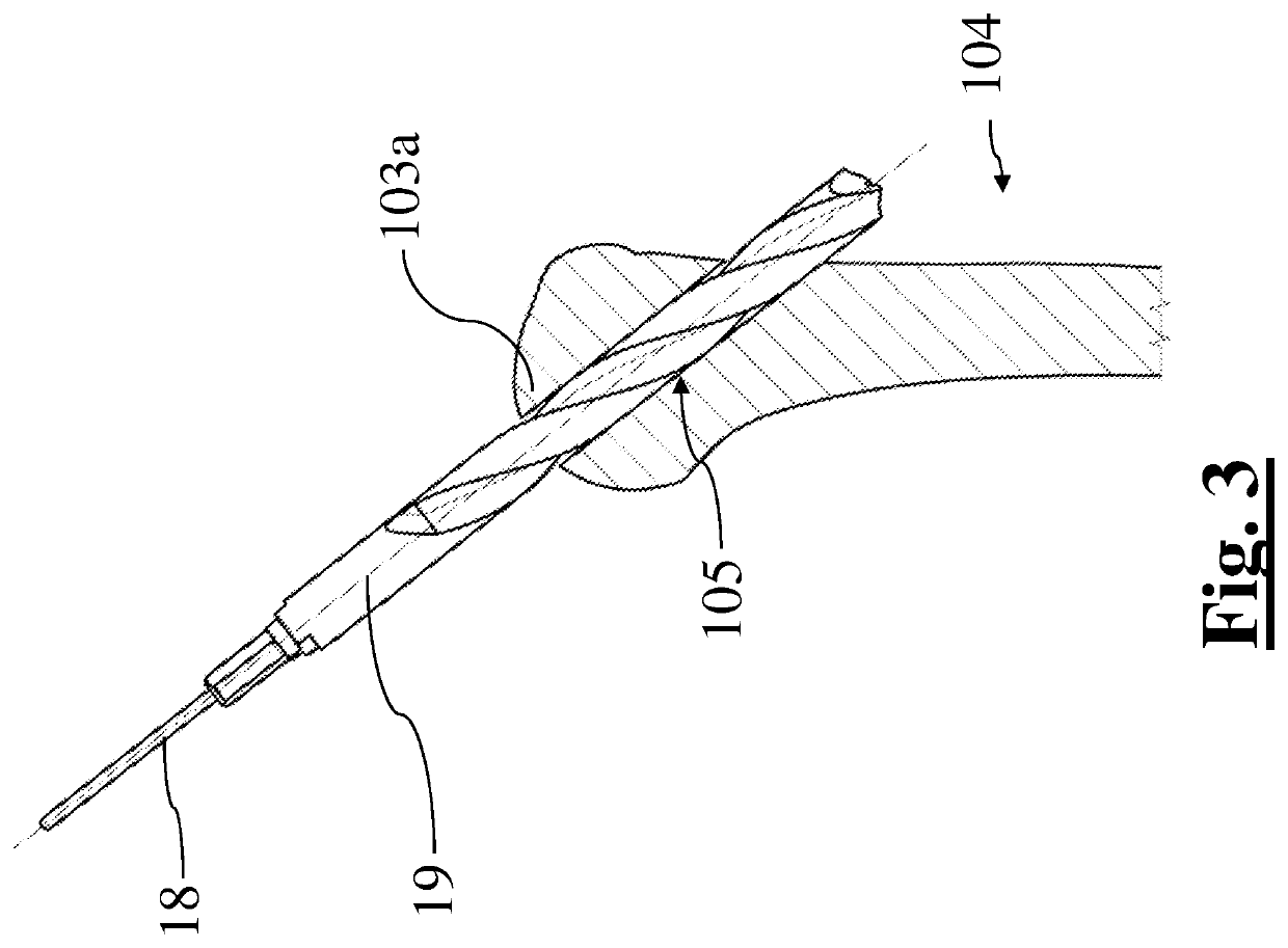
[0047]In this way, it is possible to use a plurality of machining tools to perform different machining jobs on the glenoid cavity exchanging tool without each time remove and replace the guidewire.

Problems solved by technology

Because the contact between the scapula and the humeral head is achieved in a plane parallel to the sagittal plane of the patient, the surgeon cannot visualize the contact surfaces of the glenoid cavity and the humeral head top.
Although advantageous in various respects and substantially meeting needs, the surgical technique described above has a major drawback relating to the invasiveness due to the exposure of the glenoid cavity.
If the subscapularis is released during the surgery to expose the glenoid cavity, the function of said important muscle will be compromised until the tendon that connect the muscle to the bone is not completely healed.
With the risk that said muscle does not heal well compromising forever its functionality and increasing the probability of implant failure.

Method used


Image

  • Method for surgical application of a glenoid prosthesis component of a shoulder joint prosthesis and relating surgical instruments
  • Method for surgical application of a glenoid prosthesis component of a shoulder joint prosthesis and relating surgical instruments
  • Method for surgical application of a glenoid prosthesis component of a shoulder joint prosthesis and relating surgical instruments

Examples


Embodiment Construction

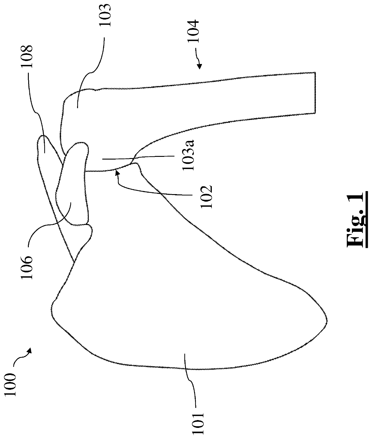
[0091]As already mentioned above, the method and the instruments according to the present invention, which will be described in detail below, are applicable to implant a glenoid anchor or glenoid component of a shoulder joint prosthesis, which could be whatever type of shoulder joint prostheses with whatever type of glenoid component. In particular, it does not exclude the application of the method and the instruments of the present invention to the implant of a reverse shoulder prosthesis. Furthermore, each instrument according to the present invention could be used in the surgery of other joints such as hip, knee, spinal column, etc.

[0092]However, the method and the instruments are described below with reference to the implant of a glenoid component of an anatomical total shoulder prosthesis, such as that one shown in FIG. 18, having a glenoid component comprising a glenoid anchor and a bearing fixed on it, but only by way of a non-limiting example and for the purpose of simplific...


PUM


Abstract

The invention relates to a method for surgical application of a glenoid anchor of a shoulder joint prosthesis and instruments advantageously used in the method. The method includes making a delto-pectoral incision providing a delto-pectoral access to a shoulder joint; with the delto-pectoral access being suitable for inserting at least one machining tool; and making a trans-deltoid incision providing a trans-deltoid access to the humeral head; with the trans-deltoid access being suitable for inserting a stem of a machining instrument to be mounted on the machining tool for machining the glenoid cavity.

Description

DESCRIPTION[0001]The present invention relates to a method for surgical application of a glenoid prosthesis component, in particular, a glenoid anchor of a glenoid prosthesis component.[0002]The principles of the present invention are applicable to different types of shoulder joint prostheses with different types of glenoid components, but the description which follows is provided with more specific reference to an anatomical shoulder prosthesis having a glenoid component comprising a glenoid anchor and a bearing fixed on it, without this however implying any limitation of the Applicant's rights.[0003]The present invention also relates to a retractor instrument suitable for keeping a predetermined glenohumeral clearance between a humeral head and a glenoid cavity of a shoulder blade; said retractor instrument is suitable for being advantageously used in the method according to present invention. It does not exclude the application of the retractor instrument in the surgery of other ...

Claims


Application Information

Patent Timeline
Patent Type & Authority Patents(United States)
IPC IPC(8): A61F2/40A61F2/30A61B17/17A61F2/46A61B17/16
CPCA61F2/4612A61B17/16A61F2/30749A61F2/40A61F2/4059A61F2/4081A61F2/4601A61F2/4014A61F2002/30332A61F2002/30405A61F2002/30878A61F2220/0008A61F2220/0025A61B17/1778A61B17/1684A61B17/02A61B17/1615A61B17/1659
Inventor PATERSON, PAULPRESSACCO, MICHELEFATTORI, ANDREADOSSO, MARCO
Owner LIMA CORPORATE SPA
Why Eureka
Try Eureka