Pneumatic fender and manufacturing method therefor

a pneumatic fender and manufacturing method technology, applied in the field of pneumatic fenders, can solve the problems of inability to ensure the expansion of the body to a predetermined shape, the circumferential region between the hemispherical portion and the body portion does not expand greatly in diameter smoothly, etc., to achieve the effect of convenient expansion, efficient manufacturing, and suppression of the difference in rigidity of the body in the circumferential direction

Active Publication Date: 2022-04-12
THE YOKOHAMA RUBBER CO LTD
View PDF13 Cites 0 Cited by
  • Summary
  • Abstract
  • Description
  • Claims
  • Application Information

AI Technical Summary

Benefits of technology

[0009]According to the pneumatic fender according to embodiments of the present invention, not only the reinforcing layers constituting the body portion, but also the bonding members disposed in each space between the reinforcing layers and the reinforcing layers constituting the hemispherical portion and disposed facing the reinforcing layers have a bias structure in which the cords layered adjacently intersect each other. In the neutral state where the body is not expanded, the cord angle of the reinforcing layer of the body portion is set to 25° or more and 45° or less, and the cord angle of the reinforcing layer is set to be approximately identical to the cord angle of the bonding member. Accordingly, when the body is filled with air and loaded with the specified internal pressure, since the cord angle of each of the reinforcing layer of the body portion and the bonding members will increase to approximately a stable angle of repose, the body portion and the boundary region between the body portion and the hemispherical portion will also easily expand. Furthermore, since the respective spaces have a plurality of different types of sizes, one set of ends of the spaces are set to a plurality of different positions, and the other set of ends of the spaces are also set to a plurality of different positions, with respect to the circumferential direction of the hemispherical portion having an arcuate shape in a side view of the body. Thus, since the bonding positions between the bonding members and the respective reinforcing layers are dispersed with respect to the circumferential direction, the difference in rigidity of the body in the circumferential direction is suppressed. Accordingly, when the body is loaded with the specified internal pressure, the strain occurring at or near the boundary between the body portion and the hemispherical portion is rectified, and it becomes easy to obtain the body that has been expanded to a predetermined shape.
[0010]According to the method of manufacturing the pneumatic fender according to embodiments of the present invention, after a multilayer structure of the reinforcing layers constituting the body portion and a multilayer structure of the reinforcing layers constituting the hemispherical portions are separately formed using a molding mold for the body portion having a cylindrical shape and a molding mold for the hemispherical portion having a bowl shape connected to both ends of the molding mold for the body portion, the multilayer structures are bonded by the bonding member to form a reinforcing body formed of the reinforcing layers. Accordingly, the pneumatic fender described above can be efficiently manufactured.

Problems solved by technology

Thus, even when the body is loaded with the specified internal pressure, the boundary region between the hemispherical portion and the body portion does not expand greatly in diameter smoothly.
As a result, since strain occurs at or near the boundary between the hemispherical portion and the body portion, a body that has been expanded to a predetermined shape cannot be ensured.

Method used


Image

  • Pneumatic fender and manufacturing method therefor
  • Pneumatic fender and manufacturing method therefor
  • Pneumatic fender and manufacturing method therefor

Examples


Embodiment Construction

[0021]A pneumatic fender and a method of manufacturing the same according to embodiments of the present invention will be described below with reference to the drawings.

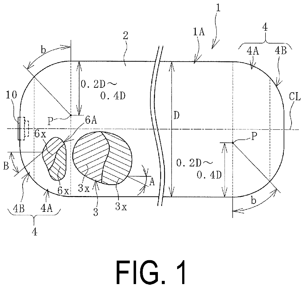
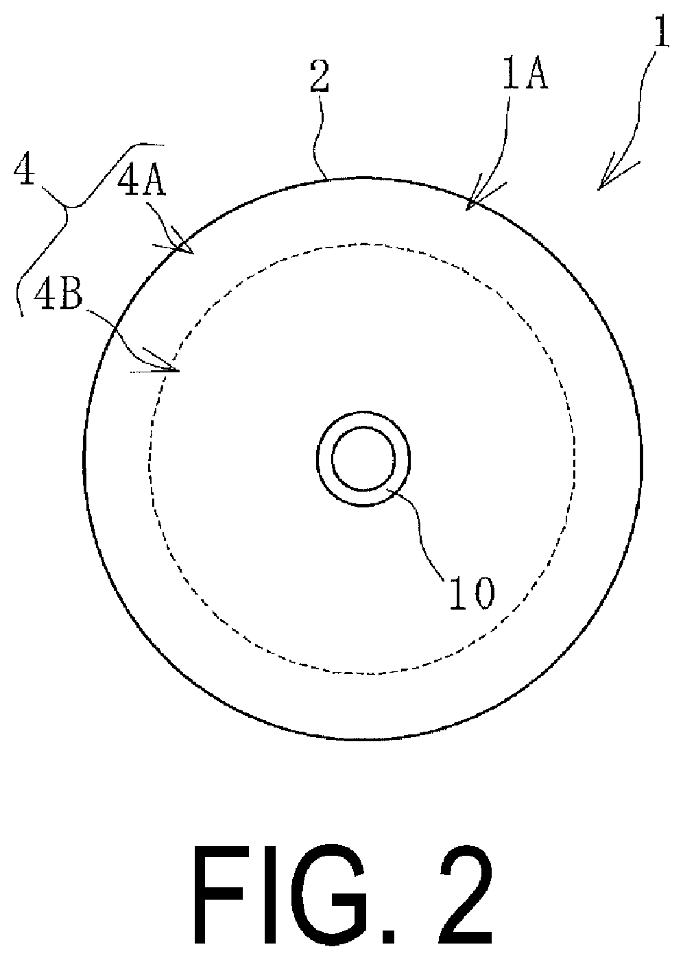
[0022]A pneumatic fender 1 (hereinafter referred to as a fender 1) according to embodiments of the present invention illustrated in FIGS. 1 to 5 includes a body 1A having a hemispherical portion 4 having a bowl shape connected to both ends of a body portion 2 having a cylindrical shape, and a mouthpiece portion 10 provided on the body 1A. In this embodiment, the mouthpiece portion 10 is provided on one of the hemispherical portions 4, but may be provided on both hemispherical portions 4.

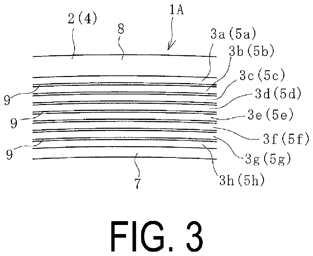
[0023]As illustrated in FIG. 3, the body portion 2 is formed by layering a plurality of reinforcing layers 3 (3a to 3h) between an inner layer rubber 7 and an outer layer rubber 8. The hemispherical portion 4 is formed by layering a plurality of reinforcing layers 5 (5a to 5h) between the inner layer rubber 7 and the outer layer rubbe...


PUM


Abstract

A cord angle of reinforcing layers having a bias structure constituting a body portion is set to 25° or more and 45° or less in a neutral state of a body. Reinforcing layers are bonded with a bonding member interposed between the reinforcing layers, the bonding member disposed in a space between the reinforcing layers facing in the cylinder axial direction of the body portion and a hemispherical portion. The layered bonding members have the same bias structure as the reinforcing layers of the body portion. A cord angle of the bonding member is set to ±10° of the cord angle of the reinforcing layers of the body portion. The spaces have a plurality of different sizes. One set of ends of the spaces are set to a plurality of different positions, and the other set of ends are also set to a plurality of different positions.

Description

TECHNICAL FIELD[0001]The present invention relates to a pneumatic fender and a method of manufacturing the same, and particularly, relates to a pneumatic fender and a method of manufacturing the same in which the boundary region between a body portion and a hemispherical portion is expanded smoothly together with the expanding body portion when a body is loaded with a specified internal pressure to make it easier to ensure the body with a predetermined shape.BACKGROUND ART[0002]Pneumatic fenders typically include a body provided with a hemispherical portion having a bowl shape at both ends of a body portion having a cylindrical shape, and the body is constituted by a plurality of reinforcing layers layered between an inner layer rubber and an outer layer rubber. In the body portion, each of the reinforcing layers is formed of multiple cords aligned in parallel, and the cords are disposed at a predetermined cord angle with respect to the cylinder axial direction. The cords of the rei...

Claims


Application Information

Patent Timeline
Patent Type & Authority Patents(United States)
IPC IPC(8): B63B59/02E02B3/26
CPCB63B59/02E02B3/26B63B2059/025Y02A30/30
Inventor TSUCHIYA, KOUKO
Owner THE YOKOHAMA RUBBER CO LTD
Why Eureka
Try Eureka