
Vehicle driver feedback system and corresponding method

a technology for driver feedback and vehicle, which is applied in the direction of external condition input parameters, instruments, transportation and packaging, etc., can solve the problems of increasing fuel cost, increasing fuel consumption, and increasing the cost of further fuel economy improvement,

Active Publication Date: 2022-04-12
VOLVO LASTVAGNAR AB
View PDF24 Cites 3 Cited by
  • Summary
  • Abstract
  • Description
  • Claims
  • Application Information

AI Technical Summary

Benefits of technology

The patent is about a system and method that provides drivers with real-time feedback on how their actions affect a score. This helps drivers better understand when they're doing well or when they need to improve their driving habits. The feedback is displayed in real-ime, so drivers can better associate it with a specific driving occurrence and learn from their mistakes. Overall, the system aims to improve driver safety and help drivers become better drivers.

Problems solved by technology

The fuel cost is expected to rise and engine development has reached a level where further improvements in fuel economy generally are very costly to attain.
The driver's ability to improve fuel economy is however still not particularly developed.
However, the effect of the driver courses normally do not last long and the driver may fall back to the old habits.
If the driver is not familiar to the road the possibility to anticipate upcoming situations will be limited.
However, applications having a relative low display update frequency may exhibit a certain delay time.
Increased time period enables overview over a longer time period but with proportionally reduced resolution, such that the near past driving feedback is increasing difficult to interpret.
Reduced time period enables improved resolution but there is an increased risk that the driver, after having passed a driver demanding time period that requested the driver's full concentration, cannot view the relevant driving feedback corresponding to the driver demanding road section because the displayed time period does not extend so far into the past to fully cover the driver demanding road section.

Method used


Image

  • Vehicle driver feedback system and corresponding method
  • Vehicle driver feedback system and corresponding method
  • Vehicle driver feedback system and corresponding method

Examples


Embodiment Construction

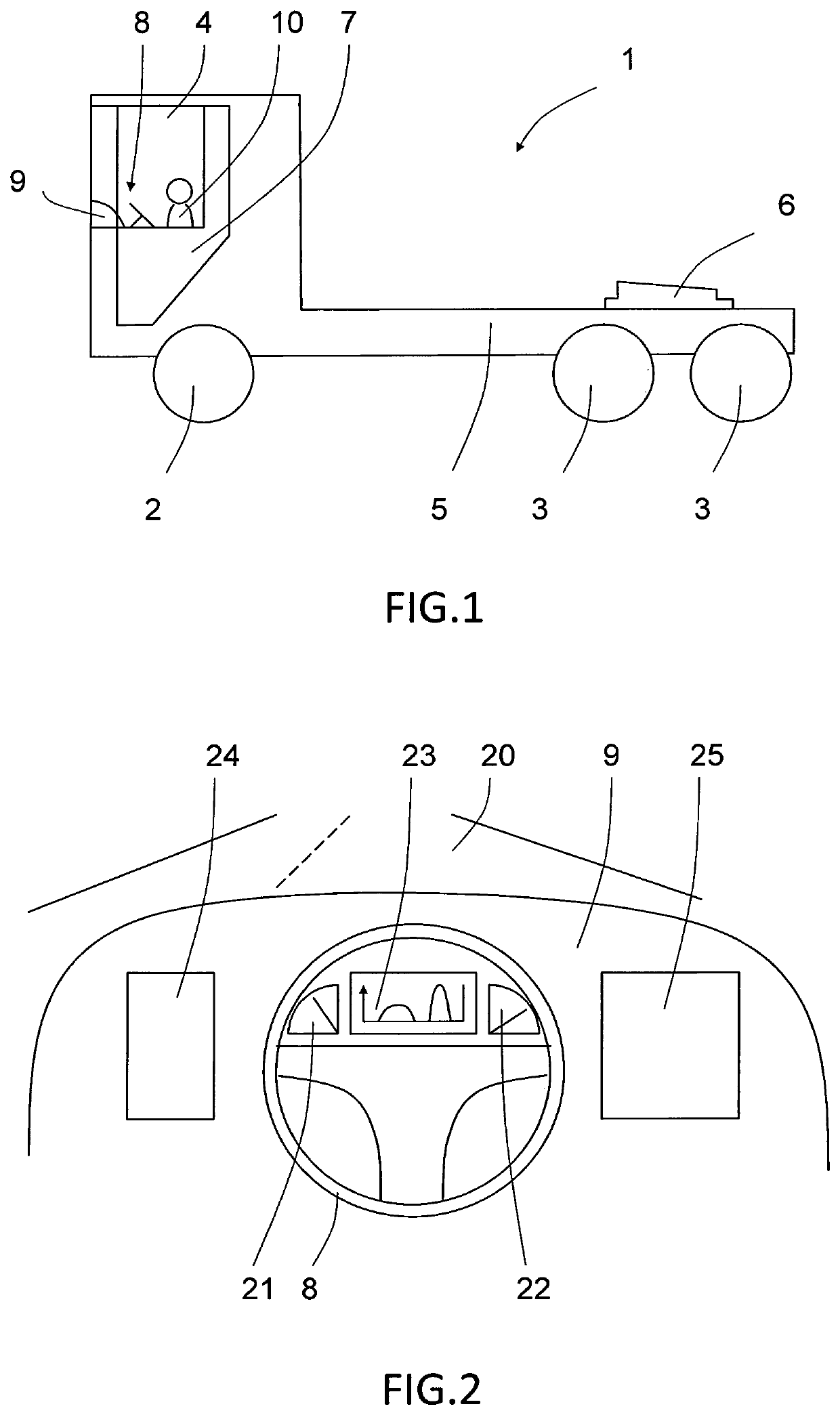
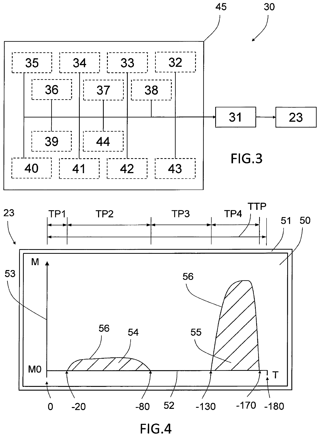
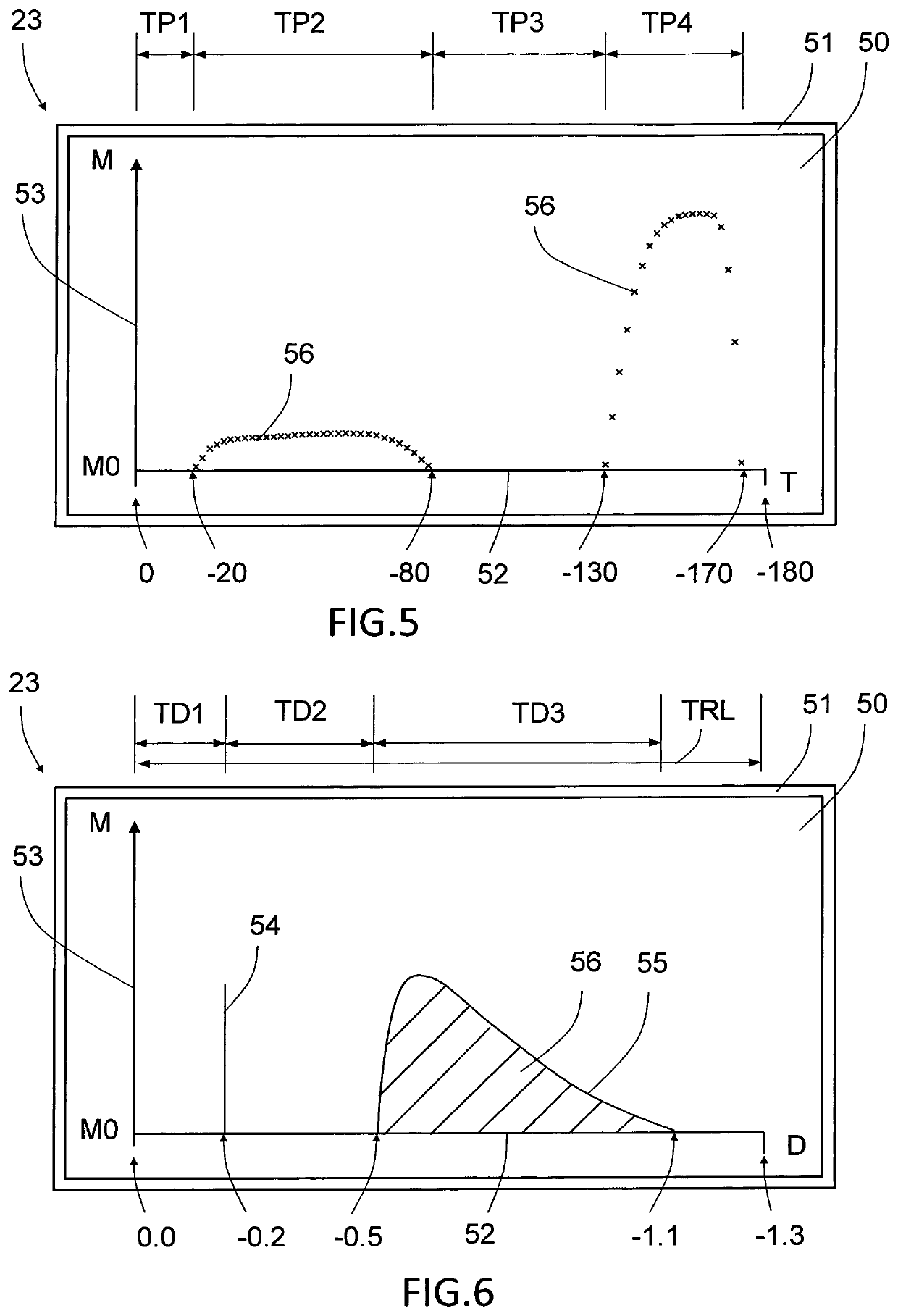
[0044]FIG. 1 shows a vehicle 1 in form of a heavy truck designed for pulling a trailer vehicle (non-showed). The truck comprises for example a pair of steering wheels 2 and two pairs of load carrying rear wheels 3, of which at least one pair is traction wheels 3. The truck further comprises a driver's cabin 4 and rear trailer receiving portion 5. The trailer may be connected to the truck by means of a trailer coupling 6. The driver's cabin 4 comprises a door 7, a steering wheel 8 and a dashboard 9. A driver 10 for driving the truck may be located within the driver's cabin. The inventive vehicle driver feedback system and method for providing a vehicle driver feedback are herein described mainly applied to a truck, such as the truck shown in FIG. 1, but the invention is not limited to only trucks and may be equally well be implemented in other types of vehicles, such as automobiles, cars, busses, construction vehicles, motorbikes, rail vehicles, and the like. The invention is also no...


PUM


Abstract

A vehicle driver feedback system includes a control unit and a display unit. The control unit is arranged for registering a driver-influenced vehicle driving parameter and the display unit is positioned in the vehicle and arranged for displaying information to the vehicle driver. The control unit further is arranged for: iteratively calculating and storing at least one score value based on the at least one driver-influenced vehicle driving parameter, wherein the at least one score value reflects a magnitude of driver-induced energy waste; driver-induced fuel waste; driver-induced vehicle wear; unsafe driving; or a weighted combination of at least two thereof, and displaying on the display unit during driving of the vehicle a graphical score value development over time or relative to the travelled route as feedback to the vehicle driver.

Description

BACKGROUND AND SUMMARY[0001]The invention relates to vehicle driver feedback system comprising a control unit and a display unit, the control unit being arranged for registering a driver-influenced vehicle driving parameter, and the display unit being positioned in the vehicle and arranged for displaying information to the vehicle driver. The invention further relates to a corresponding method for providing vehicle driver feedback comprising. The invention can preferably be applied in heavy and medium goods vehicles, trucks, buses and construction equipment, automobiles, or the like.[0002]The fuel cost is expected to rise and engine development has reached a level where further improvements in fuel economy generally are very costly to attain. The driver's ability to improve fuel economy is however still not particularly developed. With small aids a driver can reduce the total amount of fuel used simply by driving the vehicle in a more fuel efficient way. The common solution to this ...

Claims


Application Information

Patent Timeline
Patent Type & Authority Patents(United States)
IPC IPC(8): B60W50/14G09B9/042B60K35/00G07C5/06G09B5/02
CPCG09B9/042B60K35/00B60W50/14G07C5/06G09B5/02B60K2370/174B60W2520/10B60W2520/105B60W2520/125B60W2540/12B60W2554/801B60W2556/10B60W2556/50B60W2556/65Y02T10/84B60W2050/146B60K35/28B60K2360/174
Inventor SKAGIUS, ADAMLÖWGREN, FREDRIKERIKSSON, ANDERS
Owner VOLVO LASTVAGNAR AB
Learn More