Method and apparatus for motion boundary processing

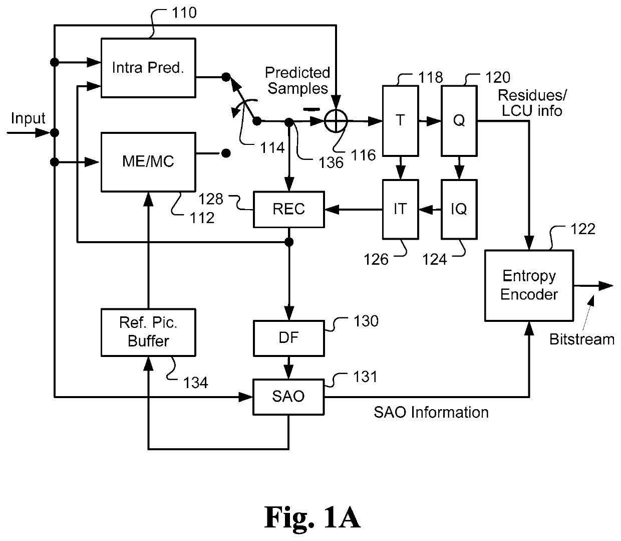
a motion boundary and processing technology, applied in the field of video coding, can solve problems such as blockiness introduction of coding artifacts, and various impairments of reconstructed video data from rec b>128/b>,

Active Publication Date: 2022-04-12
MEDIATEK INC
View PDF11 Cites 1 Cited by
  • Summary
  • Abstract
  • Description
  • Claims
  • Application Information

AI Technical Summary

Problems solved by technology

During the encoding process, coding artifacts are introduced, particularly in the quantization process.
The reconstructed video data from REC 128 may be subject to various impairments due to a series of processing.
Therefore, the pixels at the partition boundary may have large discontinuities that can produce visual artifacts similar to blockiness.
Since those partitions may have different motion vectors, the pixels at partition boundary (i.e., PU boundaries) may have large discontinuities, which may generate visual artifacts and also reduce the coding efficiency.

Method used


Image

  • Method and apparatus for motion boundary processing
  • Method and apparatus for motion boundary processing
  • Method and apparatus for motion boundary processing

Examples


Embodiment Construction

[0025]In HEVC, each coding unit (CU) may be partitioned into one or more prediction units. The OBMC is only applied to PU boundaries as described in the previous section. However, motion discontinuity may also exist at the CU boundaries as well. Accordingly, the present invention discloses a boundary pixel processing technique named motion boundary enhancement (MBE) to improve the motion compensated prediction at the CU boundaries. FIG. 4 illustrates an example according to an embodiment of the present invention. In FIG. 4A, the current CU boundaries are indicated by thicklines (410). The pixels at the CU boundaries will use the motion vector(s) from the upper side (MV_U_1), the left side (MV_L_1) or both the upper side and the left side in addition to its own motion vector (MV_X) to form a weighted sum of motion prediction when performing motion compensation. Note that MV_U_1 is the first available motion vector derived from the upper CUs and MV_L_1 is the first available motion ve...


PUM


Abstract

A method and apparatus for deriving motion compensated prediction for boundary pixels in a video coding system are disclosed. Embodiments of the present invention determine a current motion vector (MV) and one or more neighboring MVs corresponding to an above MV, a left MV, or both the above MV and the left MV. A first predictor for a current boundary pixel in a boundary region of the current CU is generated by applying motion compensation based on the current MV and a first reference picture pointed by the current MV. One or more second predictors for the current boundary pixel are generated by applying the motion compensation based on the neighboring MVs and reference pictures pointed by the neighboring MVs. A current boundary pixel predictor for the current boundary pixel is then generated using a weighted sum of the first predictor and the second predictors according to weighting factors.

Description

CROSS REFERENCE TO RELATED APPLICATIONS[0001]This application is a national stage filing under 35 U.S.C. 371 of International Patent Application Serial No. PCT / CN2014 / 093148, filed Dec. 5, 2014, which claims priority to U.S. Provisional Patent Application, Ser. No. 61 / 912,686, filed on Dec. 6, 2013, entitled “Motion Boundary Enhancement”. The Patent Applications are hereby incorporated by reference in their entirety.FIELD OF INVENTION[0002]The present invention relates to video coding. In particular, the present invention relates to method and apparatus for motion boundary processing to reduce discontinuity at coding unit boundaries.BACKGROUND OF THE INVENTION[0003]Motion estimation is an effective inter-frame coding technique to exploit temporal redundancy in video sequences. Motion-compensated inter-frame coding has been widely used in various international video coding standards. The motion estimation adopted in various coding standards is often a block-based technique, where mot...

Claims


Application Information

Patent Timeline
Patent Type & Authority Patents(United States)
IPC IPC(8): H04N19/583H04N19/51H04N19/139H04N19/105H04N19/182H04N19/573H04N19/124H04N19/13H04N19/15H04N19/186H04N19/176H04N19/96
CPCH04N19/139H04N19/105H04N19/124H04N19/13H04N19/15H04N19/182H04N19/186H04N19/573H04N19/583H04N19/176H04N19/96
Inventor HSU, CHIH-WEI
Owner MEDIATEK INC
Why Eureka
Try Eureka