Debug trace time stamp correlation between components

a technology of component correlation and trace time stamp, which is applied in error detection/correction, instruments, generating/distributing signals, etc., can solve problems such as hampered correlation

Active Publication Date: 2022-05-03
QUALCOMM INC
View PDF8 Cites 2 Cited by
  • Summary
  • Abstract
  • Description
  • Claims
  • Application Information

AI Technical Summary

Benefits of technology

[0010]The instructions, when executed by the processing system, may also configure the processing system to load a first debug time stamp counter in the first component from the first global counter in response to a first preload signal indicating awakening of the first component from a sleep state or in response to a secon

Problems solved by technology

However, such correlation is hampered because subsystem time stamp coun

Method used


Image

  • Debug trace time stamp correlation between components
  • Debug trace time stamp correlation between components
  • Debug trace time stamp correlation between components

Examples


Embodiment Construction

[0021]The word “exemplary” is used herein to mean “serving as an example, instance, or illustration.” The word “illustrative” may be used herein synonymously with “exemplary.” Any aspect described herein as “exemplary” is not necessarily to be construed as preferred or advantageous over other aspects. The term “coupled” may be used herein to mean connected via zero or more intervening elements, in contrast with the term “directly connected,” which may be used herein to mean connected via no intervening elements.

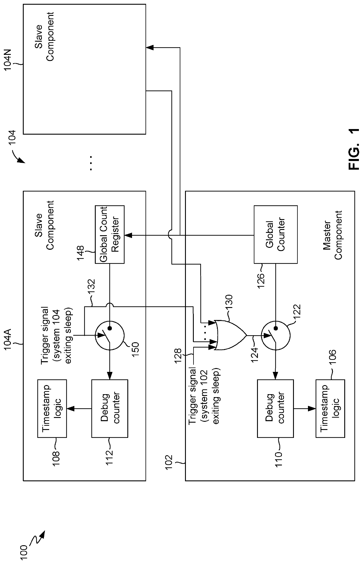
[0022]As illustrated in FIG. 1, in an illustrative or exemplary embodiment, a computing device 100 may include a master component 102 and one or more slave components 104A through 104N (collectively referred to as slave components 104). The master component 102 and each slave component 104 may be, for example, a subsystem of the computing device 100, such as, for example, a processing unit (e.g., CPU, GPU, DSP, NPU, etc.), a modem subsystem, etc. The master component 102 and ...


PUM


Abstract

Debug time stamp counters in a computing device may be synchronized based on signals indicating awakening of a component of the computing device from a sleep state. A count from a global counter in a first component may be loaded into a replica global counter in a second component. The count from the global counter may be loaded into a first debug time stamp counter in the first component in response to a first preload signal indicating awakening of the first component from a sleep state or in response to a second preload signal indicating awakening of the second component from a sleep state. The count from the replica global counter may be loaded into a second debug time stamp counter in the second component in response to the second preload signal.

Description

DESCRIPTION OF THE RELATED ART[0001]Portable computing devices (“PCD”s) are becoming necessities for people on personal and professional levels. These devices may include mobile phones, tablet computers, palmtop computers, portable digital assistants (“PDA”s), portable game consoles, and other portable electronic devices. PCDs commonly contain integrated circuits or systems-on-a-chip (“SoC”s) that include numerous components or subsystems designed to work together to deliver functionality to a user. For example, an SoC may contain any number of processing engines, such as central processing units (“CPU”s) with multiple cores, graphical processing units (“GPU”s), digital signal processors (“DSP”s), neural processing units (“NPU”s), wireless transceiver units (also referred to as modems), etc. In some complex SoCs, subsystems may be implemented using so-called “chiplet” technology. The various SoC subsystems may communicate with each other via one or more intra-chip data buses or simi...

Claims


Application Information

Patent Timeline
IPC IPC(8): G06F1/12
CPCG06F1/12G06F11/3466G06F1/14G06F11/3636G06F2201/835G06F11/3648
Inventor NARALA, NAVEEN KUMARSEVERSON, MATTHEW
Owner QUALCOMM INC
Why Eureka
Try Eureka