High strength joints between steel and titanium

a high-strength, titanium technology, applied in resistance welding apparatus, storage discharge welding, metal-working apparatus, etc., can solve the problems of not being desirable for every component, brittle intermetallic phases are formed, and the joining of titanium to other materials through welding is difficult and ineffective, and achieves greater current density

Active Publication Date: 2022-05-10
GM GLOBAL TECH OPERATIONS LLC
View PDF43 Cites 0 Cited by
  • Summary
  • Abstract
  • Description
  • Claims
  • Application Information

AI Technical Summary

Benefits of technology

[0004]The present disclosure provides a way to soundly weld titanium parts to steel parts, which is particularly useful in automotive applications, such as joining a titanium differential carrier case to a steel gear without any filler material disposed between them. Grooves may be formed into the faying surface of the steel (or the titanium) to provide greater current density on the steel side, resulting in a titanium-steel weld joint that fuses the materials together without excessively forming brittle intermetallic materials. Any undesirable intermetallics may be squeezed out during the welding process. The faying surfaces of the steel and aluminum parts may also be disposed along an angle with respect to the welding pressure axis or the axes of the parts, which also reduces the formation of intermetallic materials at the interface during a resistance welding process.

Problems solved by technology

While titanium may be desirable for certain components, it would not necessarily be desirable for every component.
However, joining of titanium to other material through welding has proven to be difficult and ineffective.
This is because brittle intermetallic phases are formed at the bonding interface, especially when attempting to weld titanium to steel.
The result is both hot and cold cracking at the weld interface and a breaking apart of the components.
These challenges make producing strong joints between titanium and steel components difficult, or even impossible.
Any undesirable intermetallics may be squeezed out during the welding process.

Method used


Image

  • High strength joints between steel and titanium
  • High strength joints between steel and titanium
  • High strength joints between steel and titanium

Examples


Embodiment Construction

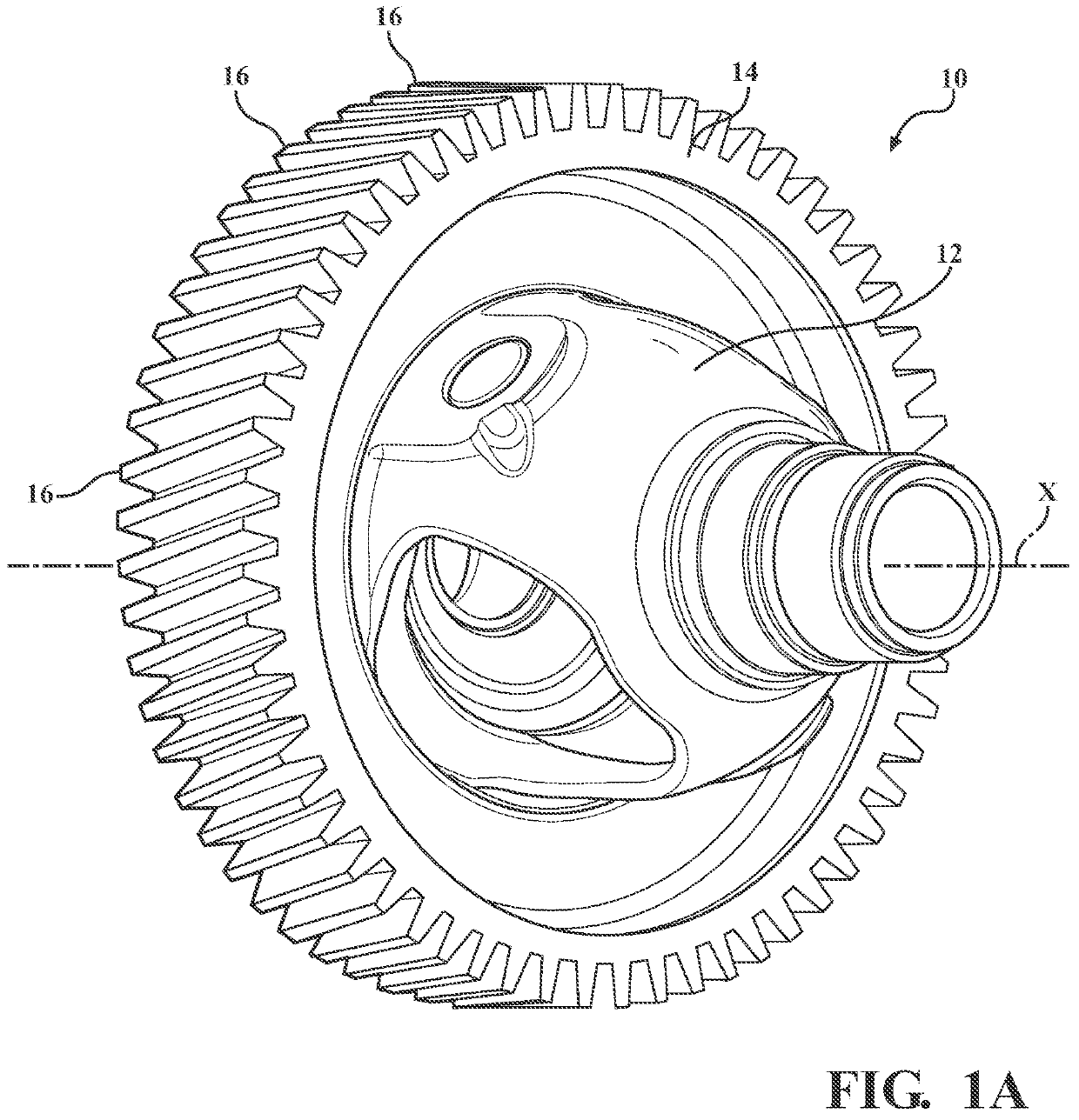
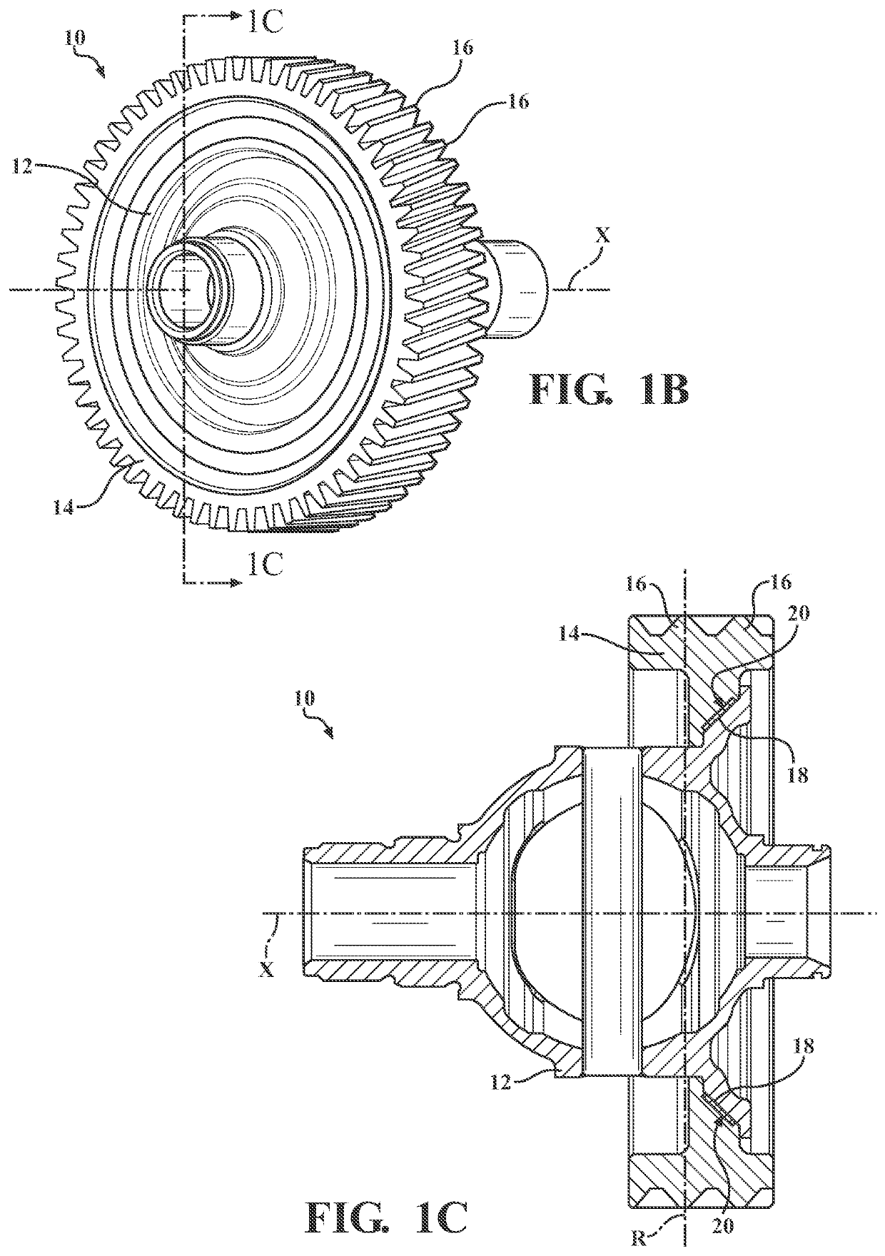
[0027]A method of resistance welding is disclosed that includes forming weld joints, or bonds, between titanium-based materials and steel. A resulting workpiece assembly is also disclosed, including a joined titanium differential carrier case and a steel gear. Providing grooves on a faying surface, as well as providing the faying surfaces at angles with respect to the axis through which pressure is applied by the welding electrodes, or at angles with respect to axes of the two parts being welded together, reduce brittle intermetallics at the faying interface and results in high strength titanium-steel joints.

[0028]Referring now to FIGS. 1A-1C, a welded assembly is provided and generally designated at 10. The welded assembly 10 includes a titanium (or titanium alloy) differential carrier case 12 welded to a steel gear 14 bearing a plurality of gear teeth 16 on an external surface thereof. A plurality of weld joints 18 join together the carrier case 12 and the gear 14 at a faying inte...


PUM

PropertyMeasurementUnit
angleaaaaaaaaaa
angleaaaaaaaaaa
angleaaaaaaaaaa

Abstract

A method of joining parts, where at least one of the parts has a faying surface defining grooves therein. One of the parts is formed of a majority of titanium, and the other part is formed of a majority of iron. The method includes providing a set of opposed welding electrodes disposed on a side of each part and applying pressure to and heating the parts via the set of electrodes to form a joint between the parts. A bonded assembly includes a first part formed of a majority of titanium and a second part formed of a steel alloy. The first and second parts having a bond that includes a portion of the first part directly in contact with and attached to a portion of the second part. The parts may be a titanium-containing differential carrier case bonded to a steel gear.

Description

TECHNICAL FIELD[0001]The technical field of this disclosure relates generally to welding of steel and titanium.INTRODUCTION[0002]Light-weighting of vehicles has been an important initiative for vehicle manufacturers to meet increasingly stringent emissions requirements. One way to reduce weight while maintaining desired strength could include producing certain components from titanium. While titanium may be desirable for certain components, it would not necessarily be desirable for every component. Accordingly, if titanium components are to be used in automobiles, they must be attached to non-titanium components. However, joining of titanium to other material through welding has proven to be difficult and ineffective. This is because brittle intermetallic phases are formed at the bonding interface, especially when attempting to weld titanium to steel. The result is both hot and cold cracking at the weld interface and a breaking apart of the components.[0003]These challenges make pro...

Claims


Application Information

Patent Timeline
Patent Type & Authority Patents(United States)
IPC IPC(8): F16H48/40C22C14/00C22C38/48C22C38/46C22C38/44B23K11/26B23K11/11B23K11/20C22C38/04B23K103/24F16H48/38
CPCF16H48/40B23K11/115B23K11/20B23K11/26C22C14/00C22C38/04C22C38/44C22C38/46C22C38/48B23K2103/24F16H2048/382C03B33/091B23K11/002B23K2101/008B23K33/006B23K33/008
Inventor LI, HUAXINBAHK, CHEONJAEGARCIA, PETE R.WILSON, DANIEL J.
Owner GM GLOBAL TECH OPERATIONS LLC
Why Eureka
Try Eureka