Welding of dissimilar materials with features in faying surface

a technology of dissimilar materials and features, applied in welding/soldering/cutting articles, manufacturing tools, mechanical equipment, etc., can solve the problems of high cost of decarburizing, difficult to produce strong joints, and inability to resist welding, and achieve the effect of increasing current density

Inactive Publication Date: 2020-10-15
GM GLOBAL TECH OPERATIONS LLC
View PDF0 Cites 1 Cited by
  • Summary
  • Abstract
  • Description
  • Claims
  • Application Information

AI Technical Summary

Benefits of technology

[0007]The present disclosure provides a way to soundly weld carburized steel parts to aluminum parts without decarburizing the steel parts. Grooves may be formed into the faying surface of the steel to provide greater current density on the steel side, resulting in an aluminum-steel weld joint that fuses the materials together without excessively melting the aluminum part and excessively forming brittle intermetallic materials. The faying surfaces of the steel and aluminum parts may also be disposed along an angle with respect to the welding pressure axis or the axes of the parts, which also reduces the formation of intermetallic materials at the interface during a resistance welding process.

Problems solved by technology

However, capacitive discharge resistance ring (CDRR) welding the various combinations of metal workpieces that may be presented in a workpiece stack-up poses certain challenges.
In addition, aluminum and steel form a series of brittle intermetallic compounds at the faying interface that, if excessively thick, can weaken the joint.
However, decarburizing is expensive.
These challenges make producing strong joints difficult, expensive, and time-consuming.
Grooves may be formed into the faying surface of the steel to provide greater current density on the steel side, resulting in an aluminum-steel weld joint that fuses the materials together without excessively melting the aluminum part and excessively forming brittle intermetallic materials.

Method used


Image

  • Welding of dissimilar materials with features in faying surface
  • Welding of dissimilar materials with features in faying surface
  • Welding of dissimilar materials with features in faying surface

Examples


Embodiment Construction

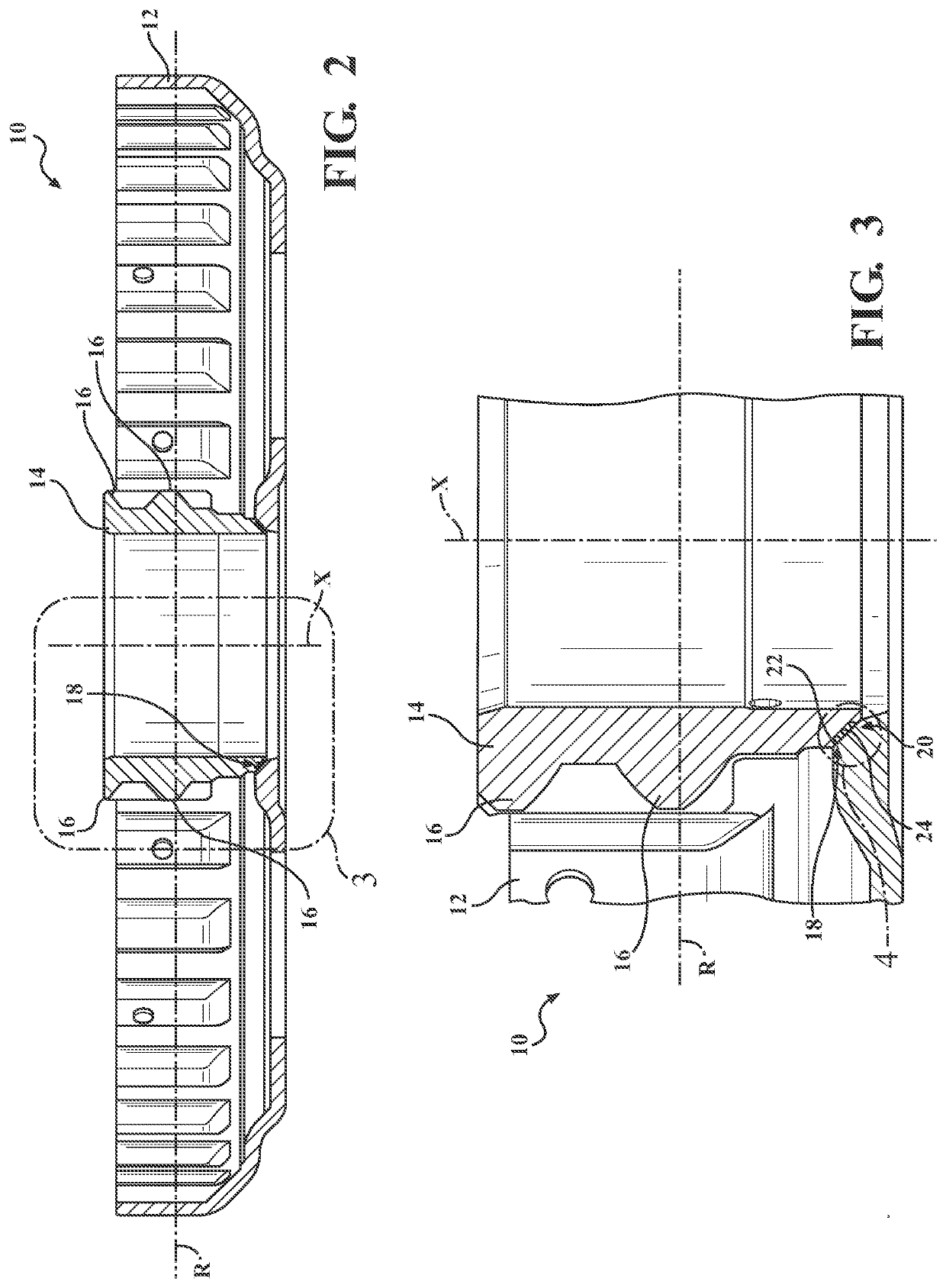
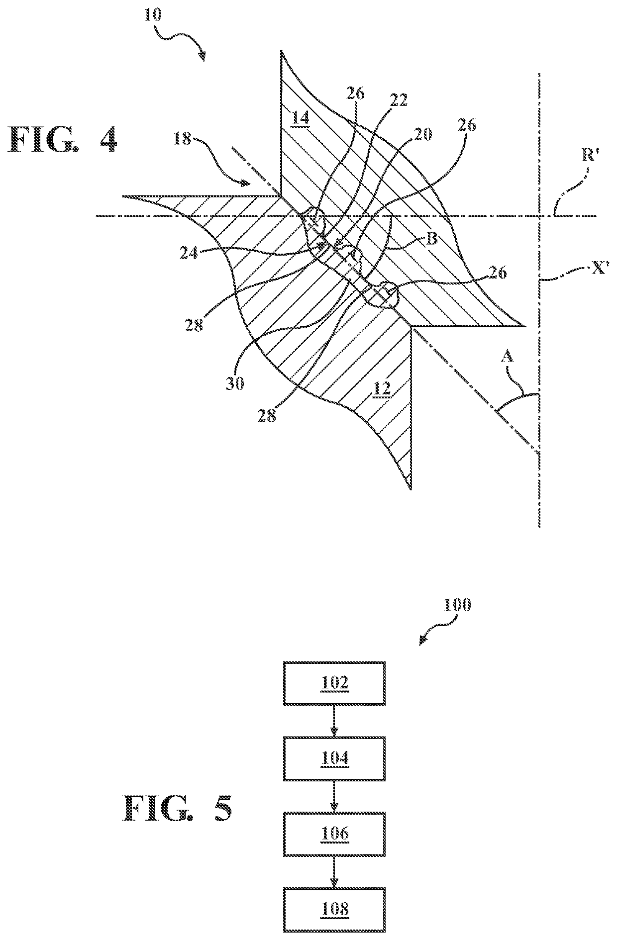
[0028]A method of resistance welding is disclosed that includes forming a number of weld joints between dissimilar materials. A resulting workpiece assembly is also disclosed. The dissimilar materials may include steel and aluminum or an aluminum alloy. In some cases, the steel may be carburized to provide good wear resistance. By providing a plurality of grooves separated by raised portions in the steel, the current density is concentrated in the steel, making it possible to adequately form the weld joints without decarburizing the steel. The weld joint may also or alternatively be facilitated by providing the faying surfaces at angles with respect to the axis through which pressure is applied by the welding electrodes, or at angles with respect to axes of the two parts being welded together, to reduce intermetallics at the faying interface.

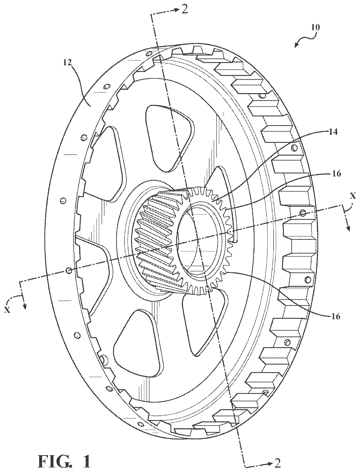
[0029]Referring now to FIGS. 1-4, a welded assembly is provided and generally designated at 10. The welded assembly 10 includes an aluminum (or...


PUM

PropertyMeasurementUnit
angleaaaaaaaaaa
angleaaaaaaaaaa
angleaaaaaaaaaa

Abstract

A method of resistance welding first and second parts formed of dissimilar materials includes disposing a first electrode on a side of the first part and a second electrode on a side of the second part. Grooves separated by raised portions are formed in a faying surface of the second part. Pressure is applied to the first and second parts via the set of electrodes, and the parts are heated via the electrodes to form a joint between the parts. A welded assembly includes metallic first and second parts welded together. The second part may have a faying surface defining a number of grooves separated by raised portions. The faying surfaces of the parts may be disposed at 10-80 degree angles with respect to a first part axis (and/or a welding pressure axis).

Description

TECHNICAL FIELD[0001]The technical field of this disclosure relates generally to resistance welding of dissimilar materials.INTRODUCTION[0002]Capacitive discharge resistance ring (CDRR) welding is a well-known joining technique that relies on resistance to the flow of an electrical current through overlapping metal workpieces and across their faying interface(s) to generate the heat needed for welding. To carry out such a welding process, a set of opposed welding electrodes is clamped at aligned rings on opposite sides of the workpiece stack-up. Electrical current is then passed through the metal workpieces from one welding electrode to the other. Resistance to the flow of this electrical current generates heat within the metal workpieces and at their faying interface(s). When the workpiece stack-up includes similar metal workpieces, such as two or more overlapping steel workpieces, the generated heat creates a molten layer at layer interface(s) and thus extends through all or part ...

Claims


Application Information

Patent Timeline
Patent Type & Authority Applications(United States)
IPC IPC(8): B23K11/20B23K11/00B23K11/02B23K11/11
CPCB23K11/002B23K11/20B23K11/115B23K11/02B23K2101/008B23K11/26B23K2103/20
Inventor LI, HUAXINNARKAR, JAHNAVIREYNOLDS, CRAIG D.
Owner GM GLOBAL TECH OPERATIONS LLC
Why Eureka
Try Eureka