Keyswitch structure

a keyswitch and keypad technology, applied in the field of magnetic keyswitch, can solve the problems of screen affecting the keypad, damage, and keyboards of conventional notebook computers not designed to have keycaps

Active Publication Date: 2022-05-10
DARFON ELECTRONICS CORP
View PDF65 Cites 2 Cited by
  • Summary
  • Abstract
  • Description
  • Claims
  • Application Information

AI Technical Summary

Benefits of technology

[0003]The present disclosure provides a keyswitch structure, which is operable to increase the distance between two magnetic parts used for providing a restoration force to a keycap of the keyswitch structure, so that the keycap can move downward for storage.
[0005]Compared with the prior art, in the keyswitch structure according to the present invention, the keycap can move downward for storage even though the keycap does not receive external pressing force thereon. Furthermore, the restoration force (i.e. the magnetic attraction force) to the keycap is not produced by an elastic structure, so the keyswitch structure will not have the problem in the prior art that the elastic member may involve a permanent deformation affecting the elasticity of the elastic member.

Problems solved by technology

The keyboards of conventional notebook computers are not designed to have keycaps that can be moved downward for storage.
Because the keycaps of the conventional notebook computer does not move downward for storage, the display screen may impact the keycaps and therefore get damaged.
Furthermore, the keyboard occupies relatively more space, which limits the thinner development of the notebook computer.
Furthermore, if the keyswitch of the keyboard is designed to use an elastic member (e.g. a rubber dome) for providing a restoration force to the keycap, when the keycap is forced to move downward for storage, the elastic member, in principle, will be at a status of being pressed for a long time, which may induce a permanent deformation affecting the elasticity of the elastic member and harmful to the lifespan of the elastic member.

Method used


Image

  • Keyswitch structure
  • Keyswitch structure
  • Keyswitch structure

Examples


Embodiment Construction

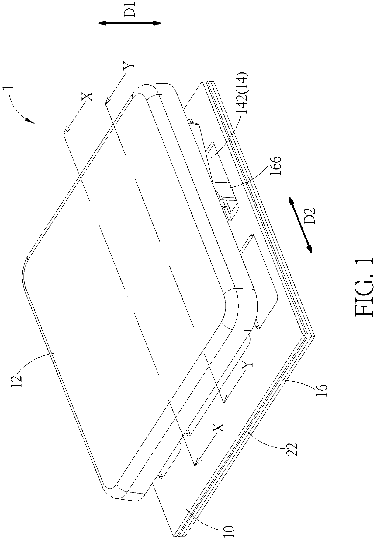
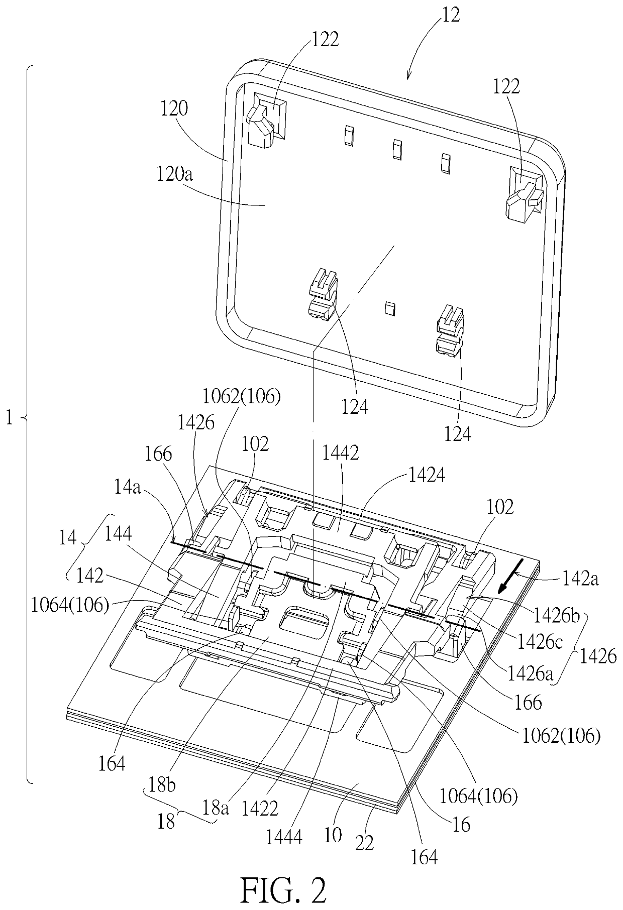
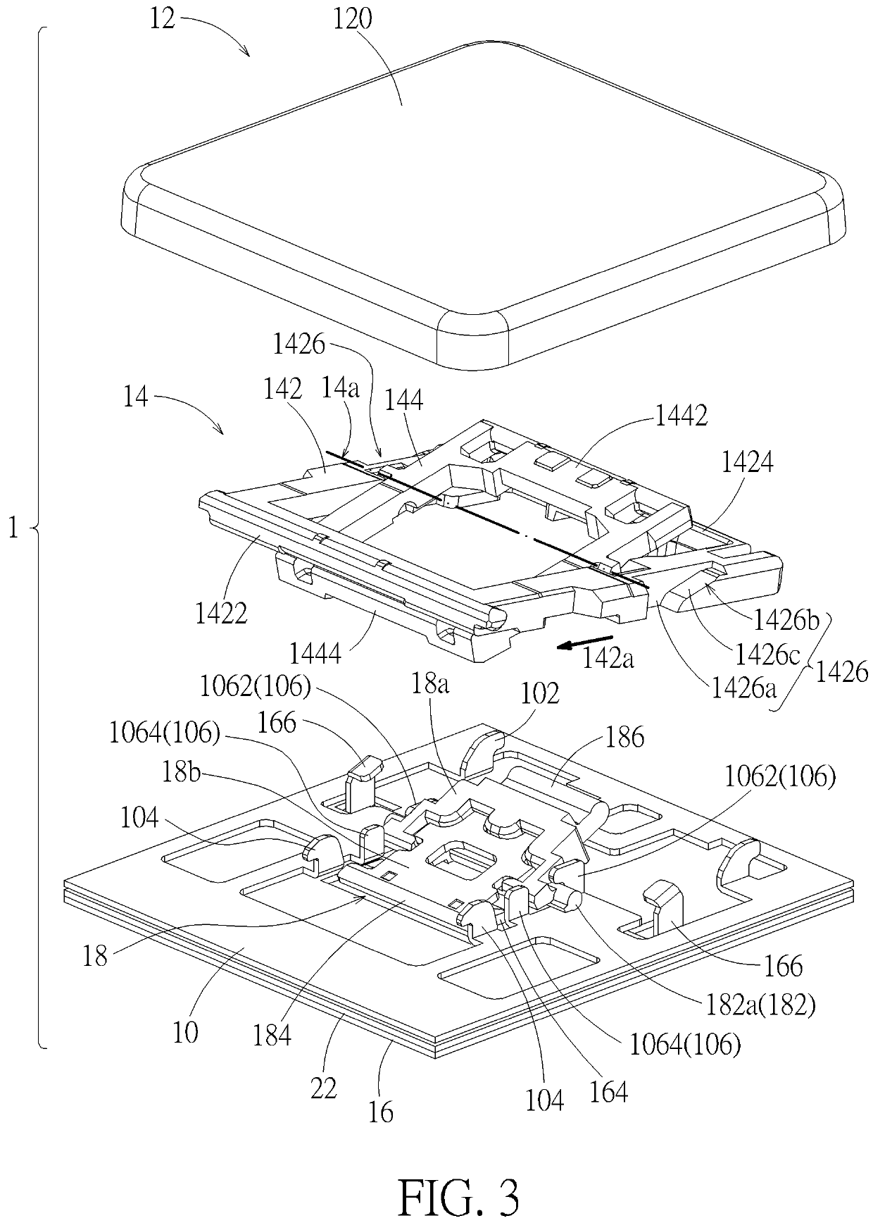
[0025]Please refer to FIG. 1 to FIG. 10. A keyswitch structure 1 according to an embodiment includes a base plate 10, a keycap12, a scissors support 14, a movable part 16, a linking support 18, a magnetic part 20, and a switch circuit board 22. The keycap 12 is disposed above the base plate 10. The scissors support 14 is disposed between the base plate 10 and the keycap 12, so that the keycap 12 can move relative to base plate 10 substantially along a vertical direction D1 (indicated by a double-head arrow in FIG. 1 and FIG. 8 to FIG. 10) through the scissors support 14. The movable part 16 is movably disposed relative to the base plate 10 substantially along a horizontal direction D2 (indicated by a double-head arrow in FIG. 1 and FIG. 8 to FIG. 10). The linking support 18 has a pivotal connection portion 182, a magnetic portion 184, and a driving portion 186. The pivotal connection portion 182 extends through the linking support 18 to two opposite sides of the linking support 18. ...


PUM


Abstract

A keyswitch structure includes a base plate, a keycap, a scissors support connecting the keycap and the base plate, a linking support rotatably disposed on the base plate, a movable part movably disposed relative to the base plate, and a magnetic part on the movable part. The linking support includes a magnetic portion and a driving portion. The magnetic part and the magnetic portion produce a magnetic attraction force therebetween. When the movable part is located at a first position, the magnetic part is located under the magnetic portion, and the magnetic attraction force drives the keycap through the linking support to move away relative to the base plate. When the movable part moves from the first position to a second position, the magnetic part moves away relative to the magnetic portion, so that the magnetic attraction force decreases so as to make the keycap move toward the base plate.

Description

BACKGROUND OF THE INVENTION1. Field of the Invention[0001]The present invention relates to a magnetic keyswitch, and more particularly to a magnetic keyswitch of which the keycap can be moved downward for storage.2. Description of the Prior Art[0002]The keyboards of conventional notebook computers are not designed to have keycaps that can be moved downward for storage. No matter whether the display screen is open or closed, the keycaps are located at the same height (i.e. the position when unpressed). Thereby, the height of the conventional keyboard is fixed. When a user has no need to use the notebook computer, the user will close the display screen. Because the keycaps of the conventional notebook computer does not move downward for storage, the display screen may impact the keycaps and therefore get damaged. Furthermore, the keyboard occupies relatively more space, which limits the thinner development of the notebook computer. Furthermore, if the keyswitch of the keyboard is desi...

Claims


Application Information

Patent Timeline
Patent Type & Authority Patents(United States)
IPC IPC(8): H01H13/14H01H3/12H01H36/00
CPCH01H13/14H01H3/125H01H2036/0086H01H1/54H01H2221/04H01H2221/068H01H2231/042H03K17/9629
Inventor HSIEH, MING-YUANYEH, LIANG-TA
Owner DARFON ELECTRONICS CORP
Why Eureka
Try Eureka