Device with steam generation function

a technology of steam generation and function, applied in steam generation plants, hand irons, light and heating equipment, etc., can solve problems such as potential safety hazards, and achieve the effect of removing potential safety hazards of existing garment steamers

Active Publication Date: 2022-05-17
ZOU JIANHAN
View PDF13 Cites 0 Cited by
  • Summary
  • Abstract
  • Description
  • Claims
  • Application Information

AI Technical Summary

Benefits of technology

[0013]1. According to the technical solution of the present application, the heating cavity has the first chamber and the second chamber which are spaced from each other in the left-right direction, the heating element is configured in the first chamber, and the steam outlet is formed in the second chamber and is spaced from the first chamber in the horizontal direction by a preset first distance, so that boiling water under the direct action of the heating element will not be directly ejected via the steam outlet like the prior art, thus eliminating potential safety hazards of the prior art;
[0014]2. The bottom wall of the first chamber is lower than the bottom wall of the second chamber, so that when there is a little water in the heating cavity, the water can be collected in the first chamber to be heated; and meanwhile, by adoption of such design, the junction of the bottom wall of the first chamber and the bottom wall of the second chamber is inclined to ensure that boiling water will not be directly ejected into the second chamber when there is a little water in the heating cavity.

Problems solved by technology

Under such configuration, steam may be directly ejected via the steam outlet when water is heated and boiled in the heating cavity, thus resulting in potential safety hazards.

Method used


Image

  • Device with steam generation function
  • Device with steam generation function

Examples


Embodiment Construction

[0019]To make the purposes, technical solutions and advantages of the implementations of the invention clearer, the technical solutions of the implementations of the invention are explicitly and completely described below in conjunction with the accompanying drawings of the implementations. Obviously, the implementations described hereinafter are merely illustrative ones, and are not all possible ones of the invention. All other implementations obtained by those ordinarily skilled in the art on the basis of the following ones without creative labor should also fall within the protection scope of the invention. Therefore, the following detailed description of the implementations provided by the accompanying drawings is not intended to limit the protection scope of the invention, and is merely used to illustrate specified implementations of the invention.

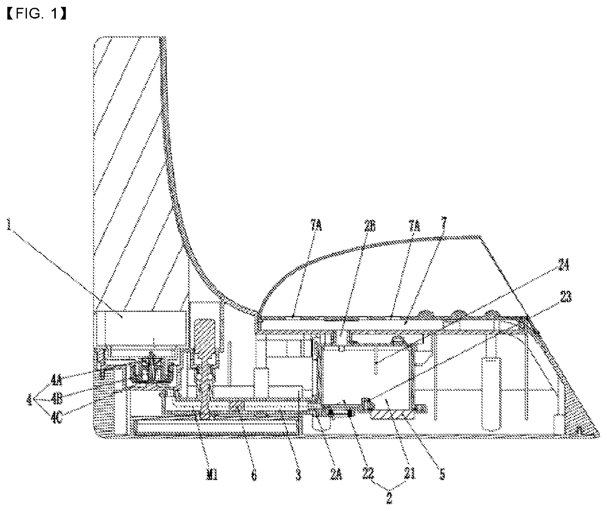
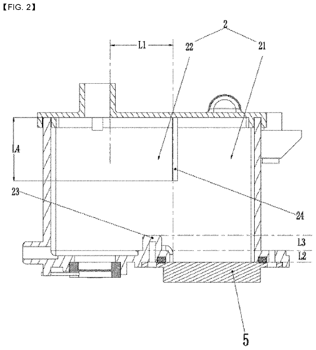
[0020]Referring to FIG. 1 and FIG. 2, in one embodiment, a device with a steam generation function provided by the present applicati...


PUM


Abstract

A device with a steam generation function comprises a water storage cavity, a heating cavity with a steam outlet, a guide channel for communicating the water storage cavity with the heating cavity, and a heating element configured in the heating cavity, wherein the heating cavity has a first chamber and a second chamber communicated with the first chamber, and the first chamber is located on one side of the second chamber; and the heating element is configured in the first chamber, and the steam outlet is formed in the second chamber and is spaced from the first chamber in the horizontal direction by a preset first distance to prevent boiling water in the first chamber from being ejected via the steam outlet. The device provided by the present invention is safe in use.

Description

CROSS-REFERENCE TO RELATED APPLICATIONS[0001]This application is a national stage of International Application No. PCT / CN2019 / 109504, filed Sep. 30, 2019, which claims the benefit of Chinese Application No. 201811147533.7, filed Sep. 29, 2018, in the China National Intellectual Property Administration, the disclosures of which are incorporated herein by reference.TECHNICAL FIELD[0002]The invention relates to a device with a steam generation function, such as a garment steamer, a steam footbath, or a hand steamer.DESCRIPTION OF RELATED ART[0003]Common devices with a steam generation function, such as garment steamers and steam footbaths, typically include a water storage cavity, a heating cavity with a steam outlet, a guide channel for communicating the water storage cavity with the heating cavity, and a heating element configured in the heating cavity. The heating element of existing garment steamers and steam footbaths is generally configured on the bottom wall of the heating cavit...

Claims


Application Information

Patent Timeline
Patent Type & Authority Patents(United States)
IPC IPC(8): F22B37/00F22B33/18D06F75/14
CPCF22B37/00F22B33/18D06F75/14D06F73/00F22B1/284
Inventor ZOU, JIANHANTANG, GUOYUNLIU, HEHAI
Owner ZOU JIANHAN
Why Eureka
Try Eureka