Gas turbine combustor and gas turbine

a gas turbine and combustor technology, applied in the direction of machines/engines, mechanical equipment, lighting and heating apparatus, etc., can solve the problems of significant thermal stress generation and uneven circumferential thermal stress applied to the base frame, and achieve the effect of reducing the concentration of thermal stress on the burner

Active Publication Date: 2022-05-17
MITSUBISHI POWER LTD
View PDF22 Cites 0 Cited by
  • Summary
  • Abstract
  • Description
  • Claims
  • Application Information

AI Technical Summary

Benefits of technology

[0004]The present invention provides a gas turbine combustor and a gas turbine that are capable of reducing the concentration of thermal stress on a burner.
[0006]The present invention makes it possible to reduce the concentration of thermal stress on a burner.

Problems solved by technology

If the temperature difference between the compressed air and the fuel is great, a significant thermal stress is generated.
Thus, the thermal stress applied to the base frame becomes uneven in the circumferential direction.

Method used


Image

  • Gas turbine combustor and gas turbine
  • Gas turbine combustor and gas turbine
  • Gas turbine combustor and gas turbine

Examples


Embodiment Construction

[0016]Embodiments of the present invention will now be described with reference to the accompanying drawings.

—Gas Turbine—

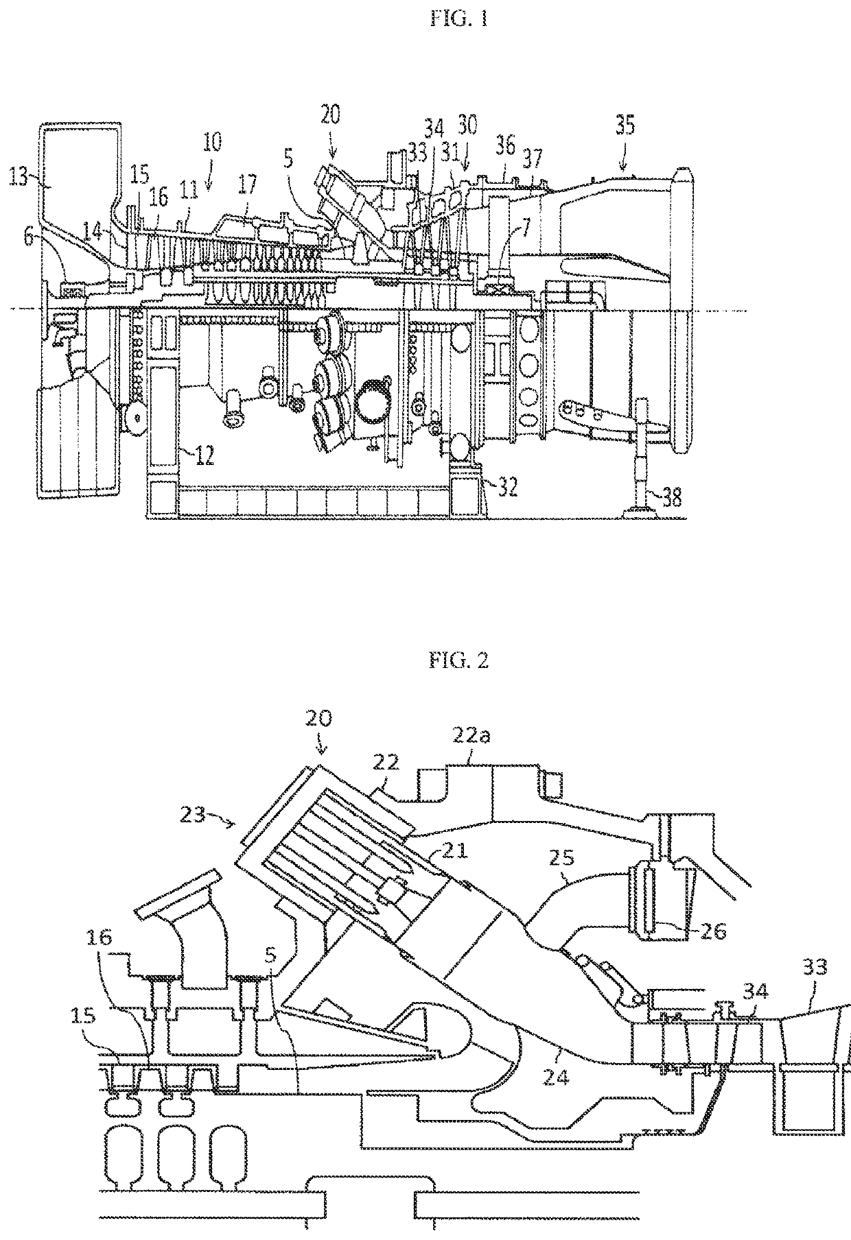
[0017]FIG. 1 is a schematic diagram illustrating an exemplary configuration of a gas turbine plant to which a gas turbine combustor according to a first embodiment of the present invention is applied. The gas turbine depicted in FIG. 1 is a prime mover that drives load equipment, not depicted, and includes a compressor 10, a gas turbine combustor, hereinafter abbreviated as the combustor, 20, a turbine 30, and an exhaust chamber 35. A compartment of the compressor 10, or compressor compartment 11, is supported by a leg 12. A compartment of the turbine 30, or a turbine compartment 31, is supported by a leg 32. The exhaust chamber 35 is supported by a leg 38. The load equipment is typically a generator. In some cases, however, a pump is the load equipment. In general, the gas turbine may be referred to as the “gas turbine engine.” In such a case, the turbine may be...


PUM


Abstract

The present invention reduces the concentration of thermal stress on a burner. A gas turbine combustor receiving compressed air from a compressor, mixing the compressed air with a fuel, burning the mixture to generate a combustion gas, and supplying the combustion gas to a turbine. The combustor includes: an inner cylinder internally forming a combustion chamber; an outer cylinder covering the inner cylinder and forming a cylindrical outer circumferential flow path between the inner and outer cylinders to allow the compressed air to flow; and a burner mounted on an end of the outer cylinder, which is positioned on an opposite side to a turbine side, and facing the combustion chamber. The burner includes a cylindrical base frame including a cavity distributing the fuel, and fuel nozzles circularly arranged as viewed from the combustion chamber and connected to the cavity. When viewed from the combustion chamber, slits extending radially are formed in the base frame such that each separate the circumferentially adjacent fuel nozzles from each other.

Description

BACKGROUND OF THE INVENTION1. Field of the Invention[0001]The present invention relates to a gas turbine combustor and a gas turbine.2. Description of the Related Art[0002]A combustor for a gas turbine receives compressed air discharged from a compressor, burns a fuel mixed with the compressed air to generate a combustion gas, and supplies the generated combustion gas to a turbine. In general, the fuel is injected into a combustion chamber from a plurality of fuel nozzles. Therefore, in some cases, the fuel nozzles are supported by a shared base frame having a cavity, or manifold, for distributing the fuel to each fuel nozzle, refer to JP-2008-025910-A and the like.SUMMARY OF THE INVENTION[0003]The base frame of the combustor is heated externally by the compressed air supplied from the compressor, and cooled internally by the fuel flowing in the base frame. If the temperature difference between the compressed air and the fuel is great, a significant thermal stress is generated. Furt...

Claims


Application Information

Patent Timeline
Patent Type & Authority Patents(United States)
IPC IPC(8): F23R3/28F02C7/22F23R3/34
CPCF23R3/286F02C7/22F05D2240/35F23D2900/00008F23D2900/14004F23R3/343F23R2900/00014F23R2900/00017F23R2900/03042F23R2900/03343F23R3/283F23R3/10F02C3/04F02C7/222F23R2900/00005F23R3/28
Inventor TSUKIDATE, HIRONORIOGA, KUNIHIROTERADA, YOSHITAKANISHIDA, KOICHI
Owner MITSUBISHI POWER LTD
Why Eureka
Try Eureka