Filter module

a filter module and filter technology, applied in the field of filter modules, can solve the problems of insufficient isolation between the wires, and achieve the effect of reducing the size of the filter module, reducing the deterioration of attenuation characteristics, and preventing the occurrence of amplification

Active Publication Date: 2022-05-17
MURATA MFG CO LTD
View PDF11 Cites 0 Cited by
  • Summary
  • Abstract
  • Description
  • Claims
  • Application Information

AI Technical Summary

Benefits of technology

[0007]Preferred embodiments of the present invention provide filter modules that are each able to significantly reduce or prevent the deterioration of attenuation characteristics while reducing the size thereof.
[0010]To provide sufficient isolation, for example, in a case where the pass band of the first filter and the pass band of the second filter are different from each other, when the communication in the pass band of the first filter is performed and the communication in the pass band of the second filter is not performed, the second wire and the ground are electrically connected by the second switch. That is, the second wire and the third input / output terminal connected to the second wire have a ground electrical potential. Therefore, the ground (third input / output terminal and second wire) is provided adjacent to or in a vicinity of the first input / output terminal and the first wire, and the deterioration of attenuation characteristics of the first filter is able to be significantly reduced or prevented. Similarly, for example, when the communication in the pass band of the second filter is performed and the communication in the pass band of the first filter is not performed, the first wire and the ground are electrically connected by the first switch. That is, the first wire and the first input / output terminal connected to the first wire have the ground electrical potential. Thus, the ground (first input / output terminal and first wire) is provided adjacent to or in a vicinity of the third input / output terminal and the second wire, and the deterioration of attenuation characteristics of the second filter is able to be significantly reduced or prevented. Further, since the number of ground terminals is not increased and the input / output terminal for a high frequency signal connected to the respective filters may also be operated as the ground terminal, a significant reduction in size is able to be provided. As described above, the deterioration of attenuation characteristics is able to be significantly reduced or prevented while providing a significant reduction in size.
[0018]For example, when the communication in the pass band of the first filter is performed and the communication in the pass band of the second filter is not performed, the second wire and the ground are electrically connected by the second switch, and the fourth wire and the ground are electrically connected by the fourth switch. That is, both of the wire connected to the input terminal of the second filter and the wire connected to the output terminal of the second filter, not one of them, are electrically connected to the ground. Therefore, the ground (third input / output terminal, fourth input / output terminal, second wire, and fourth wire) is provided adjacent to or in a vicinity of the first input / output terminal, the second input / output terminal, the first wire, and the third wire, and thus the deterioration of attenuation characteristics of the first filter is able to be further significantly reduced or prevented. Similarly, for example, when the communication in the pass band of the second filter is performed and the communication in the pass band of the first filter is not performed, the first wire and the ground are electrically connected by the first switch, and the third wire and the ground are electrically connected by the third switch. That is, both of the wire connected to the input terminal of the first filter and the wire connected to the output terminal of the first filter, not one of them, are electrically connected to the ground. Therefore, the ground (first input / output terminal, second input / output terminal, first wire, and third wire) is provided adjacent to or in a vicinity of the third input / output terminal, the fourth input / output terminal, the second wire, and the fourth wire, and thus the deterioration of attenuation characteristics of the second filter is able to be further significantly reduced or prevented.
[0025]For example, when the communication in the pass band of the first filter is performed and the communication in the pass band of the second filter is not performed, the second input terminal of the amplification circuit and the ground are electrically connected by the sixth switch. Further, for example, when the communication in the pass band of the second filter is performed and the communication in the pass band of the first filter is not performed, the first input terminal of the amplification circuit and the ground are electrically connected by the fifth switch. That is, since the first input terminal or second input terminal of the amplification circuit, which is not used for the communication, is electrically connected to the ground, malfunctioning of the amplification circuit is able to be significantly reduced or prevented.
[0028]Accordingly, it is not necessary to provide the ground terminal between the first input / output terminal and the third input / output terminal and between the second input / output terminal and the fourth input / output terminal to provide isolation between the wires connected to the respective filters, and thus a degree of freedom in design is able to be significantly increased.
[0031]With the filter modules according to preferred embodiments of the present invention, the deterioration of attenuation characteristics is able to be significantly reduced or prevented while reducing the size of the filter modules.

Problems solved by technology

Accordingly, the first wire connected to the first input / output terminal and the second wire connected to the third input / output terminal may be close to each other, and sufficient isolation between the wires may not be provided.

Method used


Image

  • Filter module
  • Filter module
  • Filter module

Examples


embodiment 1

Preferred Embodiment 1

1. Configuration of Filter Module

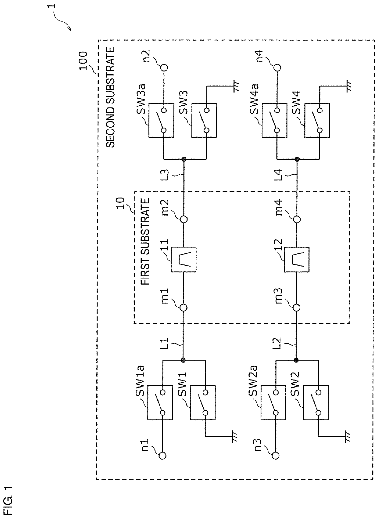
[0045]First, a filter module according to Preferred Embodiment 1 of the present invention will be described with reference to FIG. 1.

[0046]FIG. 1 is a diagram showing an example of a filter module 1 according to Preferred Embodiment 1.

[0047]The filter module 1 is a module supporting multiple bands, and supports, for example, two frequency bands. By operating the filter module 1, for example, time-division communication of signals in two frequency bands is performed. The filter module 1 includes input / output terminals n1 to n4. For example, an antenna element is connected to the input / output terminals n1 and n3, and input terminals of an amplification circuit, for example, a low-noise amplifier, are connected to the input / output terminals n2 and n4.

[0048]The filter module 1 includes a second substrate 100, a first substrate 10, switches SW1, SW1a, SW2, SW2a, SW3, SW3a, SW4, and SW4a, wires L1, L2, L3, and L4 that are provided in ...

embodiment 2

Preferred Embodiment 2

[0093]Next, a filter module according to Preferred Embodiment 2 of the present invention will be described with reference to FIG. 8.

[0094]FIG. 8 is a diagram showing an example of a filter module 2 according to Preferred Embodiment 2.

[0095]The filter module 2 according to Preferred Embodiment 2 is different from the filter module 1 according to Preferred Embodiment 1 in that switches SW5, SW6, and an amplification circuit 30 are connected to the input / output terminals n2 and n4. Other points are the same as or similar to those of the filter module 1 according to Preferred Embodiment 1, and a description thereof will be omitted.

[0096]The amplification circuit 30 has an input terminal i1 (first input terminal) connected to the filter 11, an input terminal i2 (second input terminal) connected to the filter 12, and an output terminal o1. Specifically, the input terminal i1 is connected to the switch SW5 provided between a connection node and the ground, where the c...

embodiment 3

Preferred Embodiment 3

[0105]Next, a filter module according to Preferred Embodiment 3 of the present invention will be described with reference to FIG. 10.

[0106]FIG. 10 is a diagram showing an example of a filter module 3 according to Preferred Embodiment 3.

[0107]The filter module 3 according to Preferred Embodiment 3 differs from the filter module 1 according to Preferred Embodiment 1 in that the switches SW3 and SW4, and the like are not connected to the input / output terminals m2 and m4. Other points are the same as or similar to those of the filter module 1 according to Preferred Embodiment 1, and a description thereof will be omitted.

[0108]In Preferred Embodiment 1, of the filters 11 and 12, both of the input terminal and the output terminal of the filter, which are not used for the communication, are electrically connected to the ground, but only either one of the input terminal or the output terminal may be electrically connected to the ground. Therefore, as in the filter modu...


PUM


Abstract

A filter module includes a filter provided on a path connecting an input / output terminal and an input / output terminal, a filter provided on a path connecting an input / output terminal and an input / output terminal, a switch that switches between electrical connection and electrical disconnection between a wire connected to the input / output terminal and a ground, and a switch that switches between electrical connection and electrical disconnection between a wire connected to the input / output terminal and the ground. When the wire and the ground are electrically connected by the switch, the wire and the ground are electrically disconnected by the switch, and when the wire and the ground are electrically connected by the switch, the wire and the ground are electrically disconnected by the switch.

Description

CROSS REFERENCE TO RELATED APPLICATIONS[0001]This application claims the benefit of priority to Japanese Patent Application No. 2017-254382 filed on Dec. 28, 2017 and is a Continuation Application of PCT Application No. PCT / JP2018 / 048119 filed on Dec. 27, 2018. The entire contents of each application are hereby incorporated herein by reference.BACKGROUND OF THE INVENTION1. Field of the Invention[0002]The present invention relates to a filter module.2. Description of the Related Art[0003]In recent years, development of a wireless terminal supporting multiple bands has been progressing. Whereas the number of filters to be provided increases so as to support a plurality of frequency bands, a reduction in size of the wireless terminal is demanded.[0004]Responding to the demand, for example, a filter module in which a plurality of filters is collectively provided in or on one substrate has been disclosed (for example, Japanese Unexamined Patent Application Publication No. 2005-057342). T...

Claims


Application Information

Patent Timeline
Patent Type & Authority Patents(United States)
IPC IPC(8): H03H9/54H03F3/04H03H9/17
CPCH03H9/54H03F3/04H03H9/17H03F2200/165H03F2200/171H04B1/00H04B1/40H03F2200/451H03F1/56H03F3/189H03F3/24H03H9/0547H03H9/545H03H2210/036
Inventor YASUDA, JUNPEI
Owner MURATA MFG CO LTD
Why Eureka
Try Eureka