Filter device and filter module

a filter device and filter module technology, applied in the direction of impedence networks, electrical devices, etc., can solve the problems of insufficient isolation between lines, and inability to achieve desired performance, so as to reduce or prevent the deterioration of filter insertion loss characteristics

Active Publication Date: 2019-09-26
MURATA MFG CO LTD
View PDF2 Cites 0 Cited by
  • Summary
  • Abstract
  • Description
  • Claims
  • Application Information

AI Technical Summary

Benefits of technology

[0021]According to preferred embodiments of the present invention, in filter devices in each of which a plurality of filters having different freq

Problems solved by technology

In a case in which a plurality of filters having different frequency bands are arranged on the same substrate as in Japanese Unexamined Patent Application Publication No. 2005-57342, when filters having frequency bands in proximity to each other are arranged adjacen

Method used


Image

  • Filter device and filter module
  • Filter device and filter module
  • Filter device and filter module

Examples


first preferred embodiment

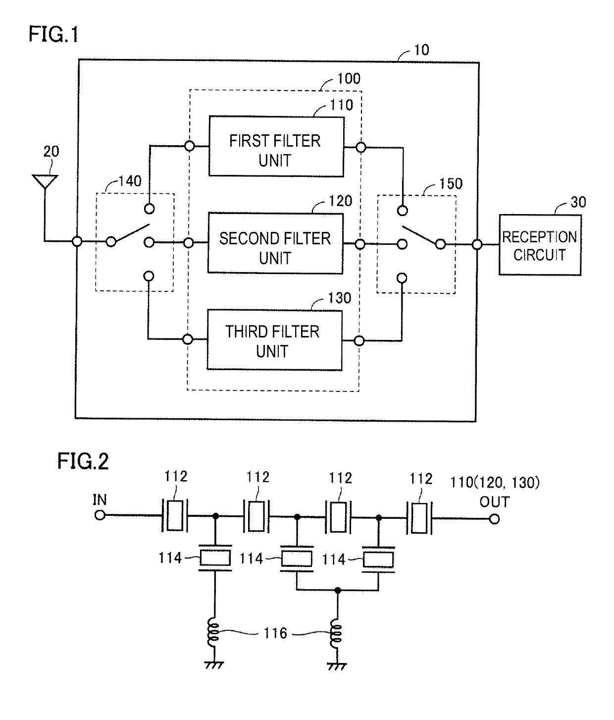
[0035]FIG. 1 is a diagram illustrating a schematic configuration of a filter device 10 according to a first preferred embodiment of the present invention. Referring to FIG. 1, the filter device 10 is a triplexer including a first filter 110, a second filter 120, and a third filter 130 which are provided on a substrate 100. The first filter 110, the second filter 120, and the third filter 130 are connected in parallel between an antenna 20 and a reception circuit 30.

[0036]In addition, the filter device 10 further includes switches 140 and 150 selectively switching one of the first filter 110, the second filter 120, and the third filter 130.

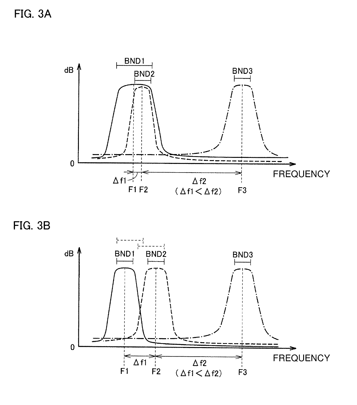
[0037]In the filter device 10, each filter extracts a signal in a passable frequency band out of the radio frequency (RF) signals received from the antenna 20 and transmits the extracted signal to the reception circuit 30. For example, the passable frequency bands of the first filter 110, the second filter 120, and the third filter 130 are preferab...

second preferred embodiment

[0059]In the first preferred embodiment, the case in which the received radio frequency signal is supplied to only the filter having the frequency band to be used of three filters has been described.

[0060]On the other hand, in recent years, carrier aggregation in which a plurality of frequency bands (lines) are simultaneously used is becoming widespread in order to increase the speed of communication. In this case, since the radio frequency signal is supplied to a plurality of filters having different frequency bands at the same time, a plurality of filters may be connected to a common antenna.

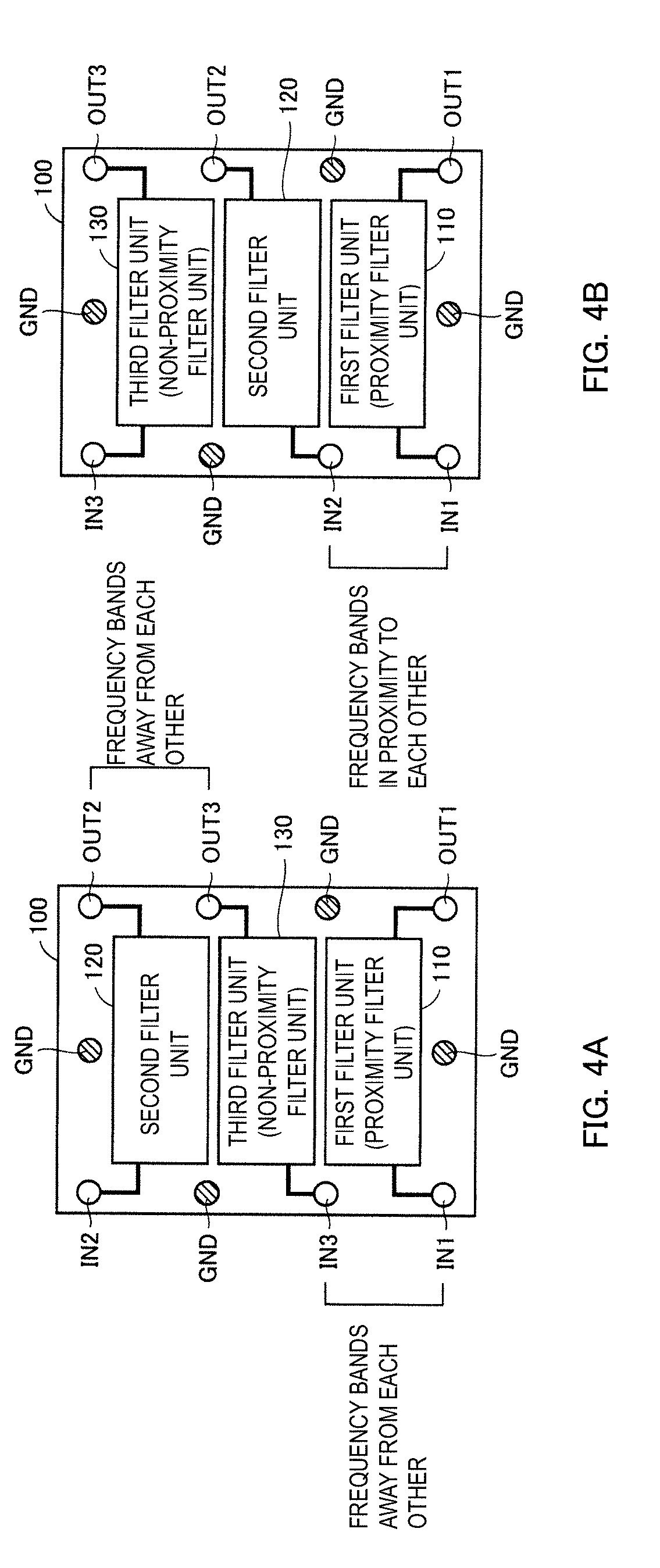
[0061]Then, since the signals that have passed through each of the filters appear at the output terminals of two filters, in a case in which the output terminals are adjacent to each other, the output signals may interfere with each other due to the electromagnetic field coupling between the terminals even when the frequency bands are not in proximity to each other.

[0062]Therefore, in a second...


PUM


Abstract

A filter device includes a substrate and first to third filters provided on the substrate and each including an input terminal and an output terminal. A center frequency of a pass band of the first filter is lower than a center frequency of a pass band of the second filter, and the center frequency of the pass band of the second filter is lower than a center frequency of a pass band of the third filter. Of the first and third filters, when the filter having the center frequency of the pass band close to the center frequency of the filter is defined as a proximity filter and the other is defined as a non-proximity filter, an input terminal and an output terminal of the proximity filter are not adjacent to an input terminal and an output terminal of the second filter.

Description

CROSS REFERENCE TO RELATED APPLICATIONS[0001]This application claims the benefit of priority to Japanese Patent Application No. 2016-251337 filed on Dec. 26, 2016 and is a Continuation Application of PCT Application No. PCT / JP2017 / 044475 filed on Dec. 12, 2017. The entire contents of each application are hereby incorporated herein by reference.BACKGROUND OF THE INVENTION1. Field of the Invention[0002]The present invention relates to a filter device and a filter module, and more particularly, to a filter module in which three or more filter devices are provided on the same substrate.2. Description of the Related Art[0003]In recent years, development of a wireless terminal corresponding to signals in a plurality of frequency bands, i.e., a multi-band wireless terminal (for example, a cellular phone or a smartphone), has progressed. In such a wireless terminal, it is necessary to include a plurality of filters adapted to the frequency to be used, and it is also necessary to reduce the ...

Claims


Application Information

Patent Timeline
IPC IPC(8): H03H9/72H03H9/02H03H9/64
CPCH03H9/02913H03H9/6483H03H9/6489H03H9/72H03H9/02992H03H9/058H03H9/6403H03H9/6433H03H9/64
Inventor YASUDA, JUNPEI
Owner MURATA MFG CO LTD
Why Eureka
Try Eureka